28.12.
Air Operated Power Brake System
As the size and weight of road vehicles increases beyond a certain level, manual brakes become inadequate and hence providing power assistance to the braking system is not meaningful as the contribution by the driver’s foot is insignificant relative to the assisted source of power, be it vacuum or hydraulic energy. Under this situation, therefore, power operated brakes become essential. The majority of heavy commercial or public service vehicles are propelled by diesel engines, which do not have a natural source of vacuum and therefore require an engine driven vacuum pump (exhauster) to supply the vacuum energy. Engine driven reciprocating compressors can operate efficiently trouble-free at pressure range of690 to 785 kPa, whereas vacuum assisted brakes can only work at the most up to 88 kPa vacuum. Therefore, compressed air has a power factor advantage of between 7 and 8 times over an equivalent vacuum energy source for transmitting a force.
The hydraulic pumps are required to work at a pressure range of 4905 to 5885 kPa and the pressures generated in the pipelines may reach valves of 9810 kPa or even more. As a result, to withstand the high pressures, small diameter servo cylinders and small bore pipes are used. It appears that use of the hydraulic energy may be a merit but, due to very high working pressure in a hydraulic operated brake system, extra care is required to avoid fluid leakage caused by wear or damage. A compressed air operated brake system requires pressures of only one-tenth of an equivalent hydraulic source, and for large vehicles where more space is available the much larger diameter cylinders can be comfortably installed. In addition, a leakage in a hydraulic system eventually drains the supply fluid making the brakes inoperable; whereas small leakages of air in an air power operated braking system do not prevent the operation of the brakes although they work at a reduced efficiency.
28.12.1.
Air over Hydraulic Brake System for Truck
Compressed air from the compressor is stored in a wet tank in a semi-dried condition. It then flows to the multi-circuit protection valve, which divides the feed to serve the two service reservoirs. Simultaneously, pressurized air from the reservoirs combines through internal passages in the multicircuit protection valve to operate the remote spring brake actuator through the hand control valve (Fig. 28.71).
Two service lines are connected to a tandem power cylinder controlled by a dual foot valve. This arrangement maintains air supply to the other circuit in case of a fault develops in one service line. The power piston push rod pushes the tandem master cylinder hydraulic piston forward so that the air pressure is converted to hydraulic pressure. The hydraulic fluid supply

Fig. 28.70. Pull-press-button and release hand-brake lever.
is divided into two circuits to serve the front and rear brake expander cylinders. A hydraulic load sensing valve is installed in the output circuit of rear axle of the tandem master cylinder. This valve appropriately proportions the braking effort provided by the rear axle based on the load carried. This is achieved by modifying the fluid pressure reaching the rear brake cylinders (Fig. 28.71).

Fig. 28.71. Truck air over hydraulic system.
In dual air and hydraulic line systems, both systems operate independently thereby safeguarding against failure of one or the other circuit. The hand control valve is used only to park the vehicle. When the hand control valve lever is moved from ‘off to ‘park’ position, air from the remote spring actuator chamber is exhausted. This causes the power spring within the actuator to expand and provide maximum pull to the rod linkage of mechanical parking brake (Fig. 28.71).
28.12.2.
Three Line Brake System for Tractor
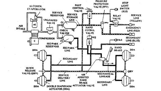
In this arrangement a separate unloader valve controls the compressor. An alcohol evaporator is installed in the air intake, which permits the introduction of alcohol into the air stream during cold weather to lower the freezing point of any water if present. During light load operation of the compressor, a check valve built into the evaporator prevents entering of alcohol into the intake air. Compressed air is then delivered to both service and secondary park reservoirs through the check valves on the inlet side of each reservoir (Fig. 28.72).
As the foot pedal is applied, air from the service reservoir flows directly to the tractor’s front and rear service line chambers located in each of the double diaphragm actuators, mounted on the tractor axles. Simultaneously, a pressure signal is received by the relay valve piston so that the valve is opened. This causes the service storage line pressure to pass from the service reservoir to the service line coupling through the pressure protection valve. Both the pressure protection valve in the service storage (emergency) line and the relay valve in the service line safeguard the tractor’s air supply, if a loss of air pressure (Fig. 28.72) occurs specifically due to a large air leak in the flexible tractor to trailer coupling hose.

Fig. 28.72. Tractor tree line brake system.
Application of the hand control valve lever delivers a controlled air pressure from the secondary park reservoir to the front wheel secondary chambers. These chambers form part of the double diaphragm actuators. The controlled air pressure is also delivered to the secondary line coupling, which in turn delivers pressurized air to the trailer brakes through a flexible hose. There is no provision of secondary braking to the tractor’s rear axle in order to reduce the risk of jack-knifing during an emergency application (Fig. 28.72).
When the hand brake lever is applied, the hand brake valve is opened and pressurized air flows to the rear axle parking line chambers within the double diaphragm actuators to apply the brakes. Simultaneously, the mechanical parking linkage locks the brake shoes in the applied position and then releases the air from the parking actuator chambers. This mechanical parking brake is therefore assisted with air (Fig. 28.72).
28.12.3.
Three Line Brake System for Trailer
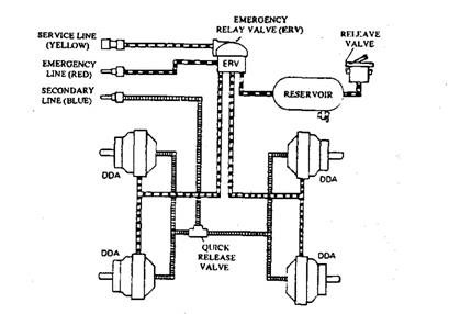
The trailer air braking system uses a own separate reservoir, fed through the emergency line from the tractor’s service reservoir. When brakes are applied, air pressure from the tractor’s relay valve energizes the emergency relay valve to open. The relay valve supplies air pressure from the trailer’s own reservoir to the trailer’s service line brake actuator chambers in proportion to the extent of application of the tractor brakes. The separate reservoir and relay valve installed in the trailer speed up the application and release of the trailer brakes, which are located at some distance from the driver’s foot control valve. If there is a reduction in emergency line pressure below some set minimum, the emergency relay valve automatically applies the trailer service brakes (Fig. 28.73).

Fig. 28.73. Trailer tree line brake system.
The hand control valve installed in front of the driver controls the secondary braking system of the trailer. The movement of the hand control valve lever in the direction of the applied position delivers a gradual air pressure through the secondary lines to the secondary chamber within each double diaphragm actuator. A quick release valve installed at the junction between the trailer’s front and rear brakes speeds up the evacuation of the secondary chambers and, therefore, the release of the secondary brakes (Fig. 28.73). When the trailer is detached from the tractor, the trailer brakes are engaged due to the evacuation of the emergency line. Therefore, a reservoir release valve is provided, which is moved to the ‘open’ piston to release the trailer brakes.
