17.8.
Air Injection System
Air injection is a method of reducing exhaust emissions by injecting air into each of the exhaust ports of an engine so that air mixes with the hot exhaust and oxidises HC and CO
forming H2O and CO2- During the early days of emission control, it was an easy task to meet the required emission standards through air injection. Air injection, also known as the air pump system (Fig. 17.28), was one of the first add-on devices to oxidise HC and CO in the exhaust. By 1966 Chrysler, the only domestic manufacturer was not using an air pump system on at least some cars. Early air injection systems used many hoses and tubes placed across the engine so that it became inconvenient to work on the engine, and hose failure due to engine heat also became common.
Chrysler chose engine modification instead of air injection and could meet emission standards without the add-on pump system. Other manufacturers also gained from Chrysler’s experience, and depended more on engine modifications and less on air injection for their cars of the late 1960′s. Therefore, the use of air injection system on cars decreased until the year 1972, when stricter emission standards were set, so that even Chrysler installed an air injection system on some engines. As emission standards became stricter during the 1970′s, air injection became more popular. Even with the introduction of catalytic converter in 1975, the air pump system could not be abandoned. It is because the extra air supplied by the injection system became useful to increase the catalytic action on many engines. With these changes, the air injection system became almost a permanent part of emission control for many engines.
Manufacturers use different names for their air injection systems, for example American Motors call it Air Guard, Chrysler names it Air Injection System, Ford calls it Thermactor Air Injection System and General Motor names it Air Injector Reactor (AIR). Irrespective of the name, all systems are simple and basically the same. A belt-driven air pump supplies fresh air to the injector nozzles installed in the exhaust manifold or cylinder head, so that air mixes with the hot exhaust leaving the engine. This helps the oxidation process necessary to reduce HC and CO emissions.
17.8.1.
Basic System Components and Operation
The basic air injection system constitutes the following components :
(i) Air supply pump with filter.
Hi) Air manifolds and nozzles.
iiii) Anti backfire valve.
(iv) Check valve.
(v) Connecting hoses.

Fig. 17.28. Typical late-model air injection system.
Air Supply Pump.
The air-pumps (Fig. 17.29), installed at the front of the engine, are belt-driven from the crankshaft. The pump draws fresh air in through an external filter and supplies it under slight pressure to each exhaust port through connecting hoses. Addition of this extra air to the hot HC and CO emissions in the exhaust manifold causes oxidation so that these constituents are converted into H2O and CO2.
The Saginaw Division of General Motors manufactured the air pumps used on all domestic cars during 1970′s. Early Saginaw pumps (1966-67) adopted a 3-vane design, which was replaced by Saginaw 2-vane design pump on 1968 and later models. The 2-vane pumps cannot be rebuilt like 3-vane design and hence are replaced whenever necessary.
The main difference between the two pump models lies in the way the intake air is filtered. The 3-vane pump drew its fresh air supply through a separate air filter (Fig. 17.30) or from the clean side of the air cleaner. The 2-vane pump has an impeller-type, centrifugal air filter fan (Fig. 17.29), fixed to the air pump rotor shaft. The air entering the pump is cleaned by centrifugal force (Fig. 17.31). The relatively heavy dust particles in the air are forced in the opposite direction to the inlet airflow, and lighter air is drawn into the pump by the impeller-type fan.
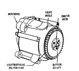
Fig. 17.29. Air pumps used on domestic vehicles (Saginaw).

Fig. 17.30. 3-vane pumps had separate inlet air cleaners.
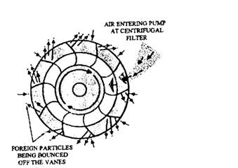
Fig. 17.31. Removal of dust and dirt from the inlet air by centrifugal force.
To control maximum pump pressure, a relief valve (Fig. 17.32) is used in many pumps and the valve opens at high engine speed. Some late-model pumps use a replaceable plastic plug to adjust the pressure setting of the relief valve. Alternatively some pumps use a diverter valve that has a built-in pressure relief valve.
Air Manifolds and Nozzles.
Early air injection systems used one of the following two methods to deliver air to the engine’s exhaust system :
(i) On smaller engines an external air manifold (Fig.
17.33) distributes the air through injection tubes to the exhaust port near each exhaust valve.
(«) On larger engines an internal air manifold (Fig.
17.34) distributes the air to the exhaust port near each exhaust valve through passages in the cylinder head or the exhaust manifold.

Fig.17.32. Air pumps with built-in pressure relief valves.
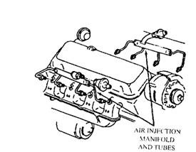
Fig. 17.33. External air manifolds for air distribution.
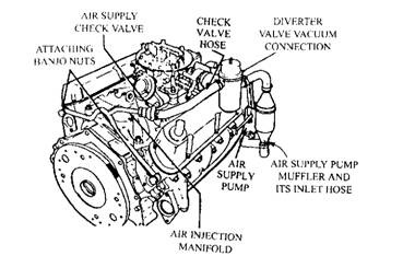
Fig. 17.34. Air distribution passages built into the cylinder heads.
The pump supplies fresh air through the air injector tubes or the manifold to nozzles in the exhaust ports. These are made of stainless steel to resist the high exhaust temperatures.
Anti-backfire Valve.
During engine deceleration, high intake manifold vacuum allows the air-fuel mixture to become fuel rich. If fresh air is supplied into the exhaust manifold during deceleration, it mixes with excess unburned fuel in the exhaust, causing engine backfire. This back fire is a rapid combustion of the unburned gases, which can blow a muffler apart. To prevent this, an anti-backfire, or backfire sup-presser, valve is incorporated to shut off the air flow during deceleration. Both gulp valve and the diverter valve are used to stop air flow.
Gulp Valve.
Early air injection system installed a gulp valve (Fig. 17.35). When intake manifold vacuum is applied to the valve diaphragm, the valve moves so that the pump air is redirected to the intake manifold to lean out the enriched air-fuel mixture during deceleration. The gulp valve is connected to the intake manifold by two hoses. The large hose supplies
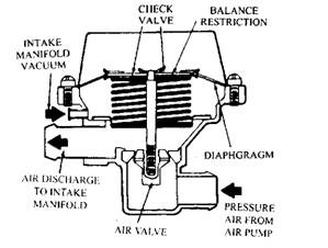
Fig. 17.35. Gulp valve.
air and the small hose provides manifold vacuum to the gulp valve to operate the diaphragm. A balance restriction, or bleed hole, placed inside the valve, equalizes pressure on both sides of the diaphragm after a few seconds. The gulp valve only remains open for a few seconds until pressure equalizes, even if the manifold vacuum is high.
Any sudden change in vaccum operates the gulp valve, which is one of the undesirable characteristics that led to its replacement. The gulp valve opens when the engine starts, which can cause hard starting and a rough idle. Also, when the throttle is closed at high speeds with low manifold vacuum, the valve may not open for a few seconds. The gulp valve, therefore, has largely been replaced by the diverter valve on late-model air injection systems.
Diverter Valve.
The diverter valve (Fig. 17.36) is also known as the dump valve or the bypass valve. Same as the gulp valve, the diverter valve has a diaphragm, which is operated by manifold vacuum to redirect the air-flow from the air pump. In this system, however, the pump air flows through the diverter valve continuously on its way to the air injection manifold. During deceleration, vacuum operates the valve diaphragm, which diverts the air directly to the atmosphere, not to the intake manifold. Some diverter valves allow the air to flow to the engine air cleaner for muffling it through a muffler and filter, built into the valve. Since diverter valves do not disturb the air-fuel mixture in the intake manifold, they cause less trouble then the gulp valves and hence are used on most late model air injection systems.
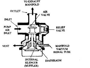
Fig. 17.36. The diverter valve.
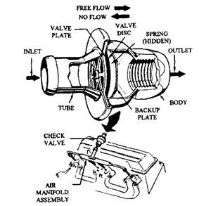
Fig. 17.37. The check valve.
Some diverter valves also incorporated a pressure relief valve to arrest the building up too much pressure in the system by air pump. This type of diverter valve is used with an air pump, which has no built-in relief valve.
Check Valve.
A 1-way check valve (Fig. 17.37) stops reverse flow of exhaust gases through the air pump from the engine. The check valve is placed in between the air manifold and the diverter valve or the gulp valve. When exhaust pressure is higher than air injection pressure, or if the air pump fails, the check valve spring closes the valve to stop the reverse flow of exhaust. A single check valve is normally used on in-line engines, and two valves (one per cylinder bank) are normally installed on V-type engines. However, some V-type engines also use only one check valve (Fig. 17.34).
17.8.2.
Second Generation Air Injection Systems
Air injection systems used with catalytic converters perform the same job, as the air injection system described above, i.e. adding fresh air into the exhaust system to oxidize the HC and CO in the exhaust gases. These second-generation systems also use many of the components of the non-catalytic systems. However, they need more elaborate controls for effective use with the catalytic converter and the design of this control varies to certain extent among the different vehicle manufacturers.
Chrysler used an air switching valve (Fig. 17.38) in their catalyst air injection system in some 1977 California engines, to switch air pump output from the exhaust ports to the right exhaust manifold. An engine coolant vacuum switch operates the valve when the coolant warms up sufficiently. This causes the valve to switch the fresh air from the exhaust ports, “downstream” to the exhaust manifold so that oxidization of HC and CO in the catalytic converter is supported without interfering with the NOx control by the EGR system. A bleed hole in the valve (Fig. 17.39) provides a small continuous airflow to the exhaust ports.
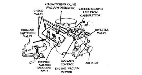
Fig. 17.38. Chrysler air switching system.
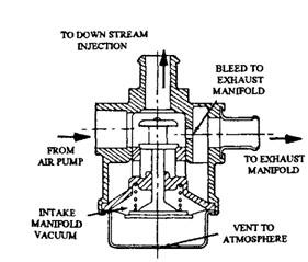
Fig. 17.39. Chrysler’s air switching valve in cutaway view.
Ford air injection system used with catalytic converter, incorporates a large-capacity air pump without a relief valve. This type pump is used on all 1975 and their later air injection systems. The system relief valve is built into the diverter valve. Ford uses three different diverter valves on their late-model systems named by them as “timed air by pass valves”.
One of the Ford valves (Fig. 17.40) works in the same way as the usual diverter valve described above. The second diverter valve was introduced in 1975 by Ford. The manifold vacuum holds this valve open to deliver air to the exhaust (Fig. 17.41). During cruising, manifold vacuum is applied to the valve diaphragm. Whereas during deceleration,
long periods of idle, and cold engine operation, vacuum is cut off from the valve and air pump output is sent to the atmosphere. Various vacuum differential valves, vacuum delay valves and bleed valves are used to control the vacuum to the diverter valve.
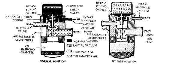
Fig. 17.40. Ford diverter valve operation.
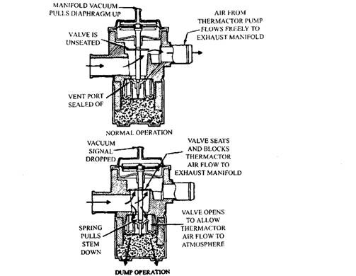
Fig. 17.41. Ford diverter valve, vacuum operated.
The vacuum differential valve (Fig. 17.42) is installed in the vacuum line connected to the diverter valve. Due to sudden changes in vacuum the differential valve redirects the vacuum to the diverter valve, which dumps the air pump output to the atmosphere. This particular diverter valve (Fig. 17.41) can also be operated with a vacuum delay valve, an air temperature vacuum switch, and a ported vacuum signal taken above the throttle plates in the carburettor.
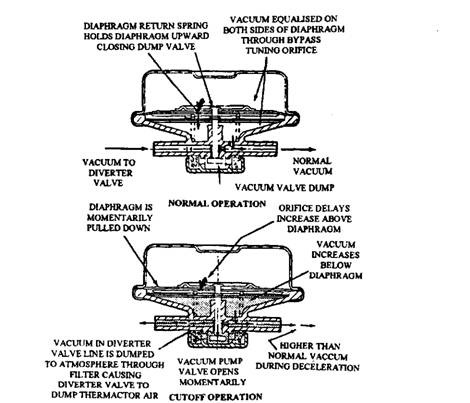
Fig. 17.42. Ford vacuum differential valve.
The third Ford diverter valve (Fig. 17.43) uses a built-in vacuum differential valve and has a vacuum vent at the top. When the vent is closed, the valve acts as a normal diverter valve. When the vent is open, any manifold vacuum above 100 mm of mercury causes the diverter valve to dump the air pump output to the atmosphere. An air temperature electric switch and an electric solenoid open the vent line at cold temperatures.
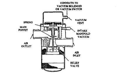
Fig. 17.43. Ford diverter valve with a vacuum vent.
General Motors air injection system has been modified on some converter-equipped engines. The air pump, the diverter valve, and the check valve are the same in both of their converter and non-converter air injection systems. In the converter system, air is injected into the exhaust pipe, downstream from the exhaust manifold (Fig. 17.44). This downstream injection supplies the air directly to the catalytic converter to help HC and CO oxidation. By keeping the air out of the exhaust manifold, the combustion chamber temperature also becomes lower, so that NOx emissions are reduced.
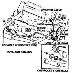
Fig. 17.44. General Motor’s converter air injection system.
17.8.3.
Pulse Air Injection
Pulse air injection systems use a pulse air valve (Fig. 17.45) in place of an air pump. This valve is similar to the check valve in an air pump system. It is a spring-loaded, diaphragm or reed valve connected to
the exhaust system. Pulse air injection was first installed on Chevrolet’s Cosworth Vega in 1975. Since then, pulse air injection has been used on GM, Chrysler, and Ford cars.
Each time an exhaust valve closes, there exists a small period in which pressure in the manifold drops below atmospheric pressure. During these low pressure (vacuum) pulses, the air injection valve opens to supply fresh air to the exhaust. When exhaust pressure rises above atmospheric pressure, the valve closes and acts as a check valve.
The pulse air injection valve performs best at low engine speed when the catalytic converter needs most the extra air. Practically the vacuum pulses occur too fast at high speed for the valve to follow, and hence the internal spring simply keeps the valve closed.
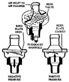
Fig. 17.45. Pulse air injection valve (Ford).
