This topic covers all you need to know about drawing lines in the AutoCAD window from VBA macros. You can draw continuous lines, dashed lines, or any other linetypes available in AutoCAD. You’ll see how to draw your lines highlighted and colored, and even how to draw parallel lines—all from code.
You’ll also learn how to develop an application one piece at a time by progressively adding some tried and tested UserForms and macros. Throughout this topic the pieces will be developed individually, and after they’re tested the application will be extended to incorporate them. Sometimes these macros will be used intact, and at other times the ideas they represent will be adapted slightly to suit.
Drawing a line from code is achieved using the AddLine method, which creates a Line object based on the two endpoints passed to it as arguments in the call. Both endpoints are specified in the World Coordinate System (WCS). This new Line object is then added to the ModelSpace collection (or PaperSpace collection).
For the examples in this topic, I’ve assumed all the drawing is done in the Model tab of the AutoCAD window, so the Model Space will be the preferred drawing space rather than the Paper Space.
Let’s create an application that allows the user to input the coordinates for both endpoints of a line and then click a button to create and draw the line. This application, Exercise 6.1, will be adapted and extended in other sections throughout this topic.
Exercise 6.1: Line Input Application
You’ll begin by creating a new UserForm that allows the user to enter the coordinates of the endpoints defining a line.
1. Start a new project in the IDE and choose Insert ^ UserForm. Double-click the Label icon in the Toolbox, and move the cursor to the top-left corner of the UserForm. The Label control’s icon follows the cross cursor as it moves.
Double-clicking a Toolbox control allows you to place multiple instances of it on a UserForm without having to return to the Toolbox each time. Click anywhere inside the Toolbox to let Visual Basic know when you’ve finished.
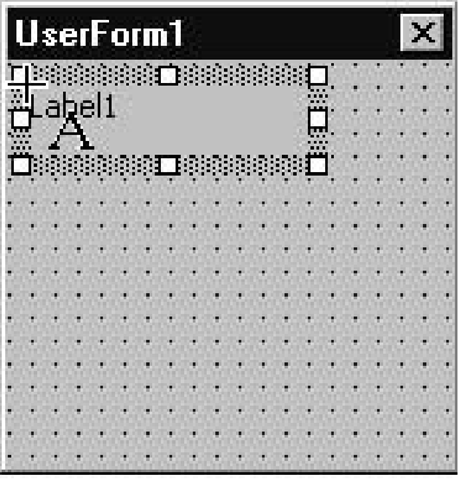
2. With the cursor still in the top-left corner, click the mouse. A default-sized Label control appears with its top-left corner positioned at the center of the cross cursor, as shown here:
Notice how the cursor is still a cross and that the Label control’s icon still follows it around after the click—this is because double-clicking Toolbox icons lets you add as many instances of a control as you like.
3. Move the cursor to roughly halfway down the UserForm, keeping it close to the left boundary. Click the mouse, and a second default-sized label appears.
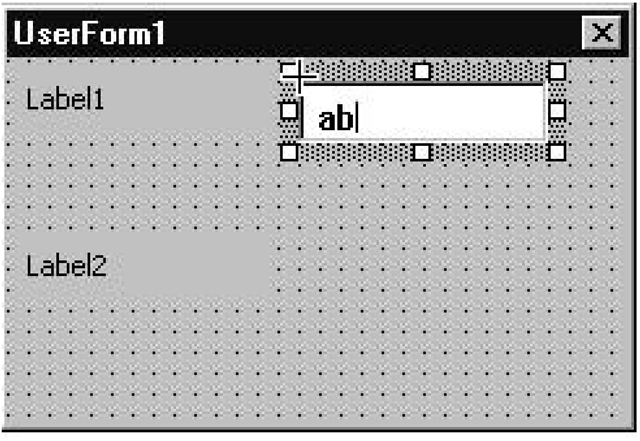
4. Double-click the TextBox control icon in the Toolbox, and click the cursor roughly in the middle and near the top of the UserForm. The mouse pointer changes from a Label control icon to a TextBox control icon, and a defaultsized TextBox control appears.
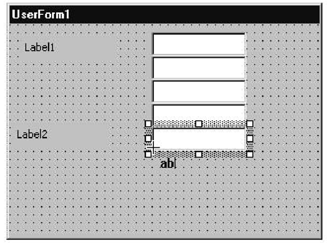
5. Position the cross cursor in the bottom-left corner of the TextBox control and click again. Repeat this until you have placed six text boxes on the UserForm, one below the other (see Figure 6.1). The six text boxes appear evenly spaced and perfectly aligned—if they’re not, use the Format command to make any small adjustments required.
6. Double-click the CommandButton icon in the Toolbox, position the cross cursor in the bottom-left corner of the sixth text box, and click. The command button appears, aligned with the text boxes.
7. Position the cross cursor in the bottom-left corner of the first command button and click. A second command button appears, aligned with the first one.
8. Change the names of the UserForm and its text box and command button controls to those shown in Table 6.1, by overtyping the names in the Properties window. (Choose View ^ Properties Window if this window is not already displayed.)
Figure 6.1 Placing TextBox controls in a UserForm so they are drawn aligned
Giving controls names that reflect their functions makes it easier to remember which control is which as the application is extended. Using the prefix naming conventions enables you to easily know the kind of control referred to by the name. In addition, it ensures that controls of the same type are listed together in the Object drop-down list in the Code window.
Table 6.1 Assigning Semantic Names to the Line Input UserForm and Its Controls
|
Old Name |
New Name |
|
UserForm1 |
frmLineInput |
|
TextBoxI |
txtStartPointX |
|
TextBox2 |
txtStartPointY |
|
TextBox3 |
txtStartPointZ |
|
TextBox4 |
txtEndPointX |
|
TextBox5 |
txtEndPointY |
|
TextBox6 |
txtEndPointZ |
|
CommandButtonl |
cmdDrawLine |
|
CommandButton2 |
cmdExit |
9. Change the Caption properties of the UserForm and its controls as shown in Table 6.2.
Table 6.2 Caption Properties for the Line Input UserForm
|
Control |
New Caption |
|
frmLineInput |
Line Input |
|
Label1 |
Enter the X,Y and Z coordinates for the start of the line. |
|
Label2 |
Enter the X,Y and Z coordinates for the end of the line. |
|
cmdDrawLine |
Draw Line |
|
cmdExit |
Exit |
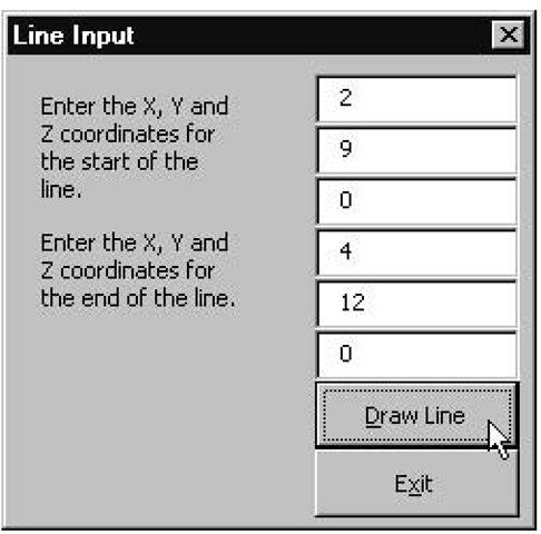
10. Change the Accelerator property of the cmdDrawLine control to D, and to x for the cmdExit control. The D and x appear underlined on the command buttons (see Figure 6.2) to indicate they can be “clicked” using the Alt+D or Alt+x key-combinations.
Figure 6.2 The Line Input UserForm with new captions and accelerator keys
The letter x is the pseudo-standard accelerator key for exiting from any Microsoft Windows application.
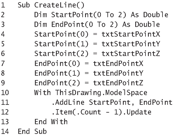
11. Enter the code shown in Listing 6.1. The CreateLine macro should be placed in the General Declarations section of the UserForm’s Code window. This procedure transfers the values from the text boxes into two arrays, which are used as arguments in the call to the AddLine method.
Listing 6.1: CreateLine Macro
Analysis
• Line 1 starts the CreateLine procedure.
• Lines 2 and 3 declare the two arrays that will hold the coordinates of the endpoints entered into the text boxes by the user. These must be arrays of the Double type so that they can be used as arguments when the AddLine method is called at Line 11.
• Lines 4 through 9 take the x-, y-, and z-coordinates input by the user into the six text box controls and assign them to the elements of the start and endpoint arrays. All the text box controls are accessed without fully qualifying them with the UserForm’s name, and the Text property is implied for all the text boxes because it is the default property for this control.
The default property of the TextBox control is Text, so when the control’s name appears in code on its own, VBA automatically assumes the Text property is required.
• Line 10 starts the With ThisDrawing.ModelSpace statement block,so that the ModelSpace collection will be used for unqualified items.
• Line 11 passes the StartPoint and EndPoint arrays as arguments to the AddLine method.This method creates a Line object defined by the coordinates passed to it and adds the object to the ModelSpace collection of objects.
• Line 12 uses the Count property to determine the number of objects currently in the ModelSpace collection. Since the index to the first object in the collection is zero, the last object is at Count -1. So the Item method is used to return the last object added to the collection (which is the line just added). The returned object’s Update method is then called to redraw the object in the AutoCAD window—so your new line appears.
• Line 13 ends the With ThisDrawing.ModelSpace statement block.
• Line 14 ends the procedure.
Exercise 6.1: Line Input Application
In the next set of steps, you’re going to code the Click event procedures for the two command buttons, code the macro that runs this Line Input application, and run the application.
1. Continuing in the UserForm’s Code window, select cmdDrawLine from the list of objects, and select Click from the list of procedures. In the skeleton Click event procedure that appears, insert the call to the CreateLine macro (Listing 6.1):
CreateLine
This Click event procedure of cmdDrawLine will run when the user clicks the Draw Line button or uses the Alt+D key-combination.
2. Place the Unload Me statement in the Click event procedure for the cmdExit command button. This event procedure runs when the user clicks the Exit button or uses the Alt+x key-combination. All the lines input by the user are already preserved in the ModelSpace collection, so there is nothing to be saved before quitting.
3. Choose Insert ^ Module. Place the following DrawLine macro in Module1’s Code window so that AutoCAD will include it in the list of macros (see step 4). The DrawLine macro uses the Show method to display the frmLineInput UserForm and thus start up the application.
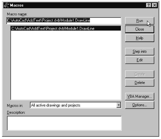
4. To run the DrawLine macro, choose Tools + Macro + Macros, select Draw-Line from the list (shown just below), and click Run. The Line Input UserForm appears. When the user clicks the Draw Line button, its Click event procedure is executed and calls the CreateLine procedure.
Every VBA project should have at least one macro so that you can kick-start the project from the Tools + Macro + Macros dialog box.
5. Enter the coordinates of a line. Use the Tab key or the Enter key to move from text box to text box in tab order. Then click the Draw Line button.
This draws the line with the coordinates just entered in the Model tab of the AutoCAD window. In the background, VBA also creates a Line object and adds it to the ModelSpace collection.
If you need information about tab order, read the next section.
6. Save your project as LineInput.
A Control’s Tablndex and TabStop Properties
The TabIndex property is assigned a numerical value that represents the order in which the object was added to the UserForm. When the UserForm is open, its controls can be given the focus in tab order by repeatedly pressing either the Tab or the Enter key. The appearance of a control when it’s given the focus depends on the control’s type. For example, when a text box is given the focus, the I-beam cursor appears inside the text box; when a command button is given the focus, its caption is enclosed in a dashed rectangle.
Although the TabIndex property of every control is allocated a number, VBA will automatically set to False the TabStop property of any controls that cannot be used for interacting with the user (such as Labels). The TabStop property determines whether or not a control is allowed to get the focus.
The With Statement
The With statement allows you to specify an item and then include it in a series of statements that use the item, without the need to qualify the item each time. Items can be an element from a user-defined type, an object, or a collection. For example:
Here, the three properties that start with a period character (. ) are all assumed to belong to the object specified in the opening With statement.
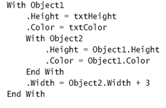
VBA allows a With statement to be nested inside another With statement, with the unqualified object assumed to belong to the object or collection specified in the With statement block to which the unqualified object belongs. So you must qualify objects in the outer With block when they are used inside the inner With block. For example:
Here, the first Height and Color properties are inside the outer With block,so Objectl is implied. The second Height and Color properties are inside the inner With block, so Object2 is implied. The Width property in the second to last statement belongs to Objectl because it lies inside the outer With block.
The advantages of using a With statement are that the code requires less typing, it is easier to read, and it will be more efficient to run, leading to improved performance.
