Creating a Box
The bounding box for a Box solid has the same vertices and edges as the Box itself. In this section you’ll see how to calculate the center of the bounding box and pass it to the AddBox method, to create the Box solid with its edges parallel to the three-dimensional WCS axes.
In Listing 15.3, the AddBox method is called from the DrawBox macro with the following arguments:
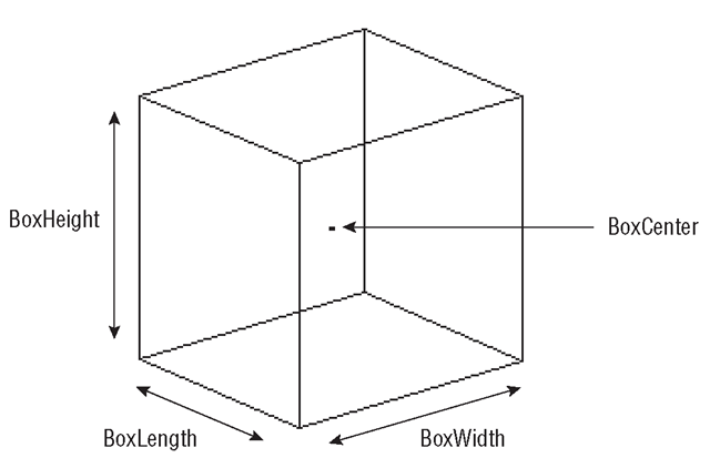
BoxCenter A three-element array that defines the coordinates of the center of the box. This is used to position the box in WCS.
BoxLength A positive value representing the length of the box.
BoxWidth A positive value representing the width of the box.
BoxHeight A positive value representing the height of the box.
Exercise 15.1 is continued in this section, taking you through the steps of entering the DrawBox macro and running it. Figure 15.2 shows the Box solid generated by the macro.
Figure 15.2 Box generated by the DrawBox macro (Listing 15.3)
Exercise 15.1: Building the 3D Solids Application
1. Continuing with Exercise 15.1, enter the DrawBox macro code (Listing 15.3) into the Code window for ThisDrawing.
2. Enter the following statement into the skeleton Click event procedure for optBox:
ThisDrawing.DrawBox
3. Run your macro from the Macros dialog box in the AutoCAD window, or you can run it from the Visual Basic Editor.
4. Follow the prompts in the command line to enter the position and dimensions required.
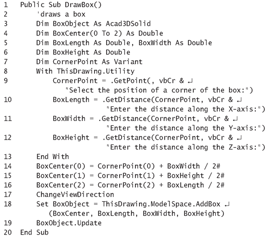
Listing 15.3: DrawBox Macro
Analysis
• Line 1 starts the DrawBox macro, which prompts the user for the position and dimensions for the box and then creates it.
• Line 3 declares the BoxObject variable as being capable of referencing a 3DSolid object. The 3DSolid object can contain any of the solid objects that are added to the drawing, using Add followed by the solid type (such as AddSphere, AddBox, and AddCylinder).
• Line 4 declares the BoxCenter array that will be assigned the center of the Box solid, which is also the center of the bounding box.
• Lines 5 and 6 declare the variables that will be allocated the three dimensions of the box along the x-, y-, and z-axes.
• Line 7 declares the CornerPoint variable as a Variant type, so that it can be allocated the three-element array containing the coordinates of the position for a corner of the box in a single statement.
• Line 8 uses the With statement block, so that the methods of the Utility object for ThisDrawing can be used without having to fully qualify them.
• Line 9 prompts the user to click on the position for a corner of the box. This will be used to determine the center of the box, which in turn defines the position for the box.
• Lines 10 through 12 prompt the user to enter the x, y, and z dimensions for the box by calling the GetDistance method to return the three values required.
• Line 13 ends the With statement.
• Lines 14 through 16 calculate the three coordinates that define the center of the box based on the corner point and the box’s dimensions.
• Line 17 calls the ChangeViewDirection macro given in Listing 15.2 so that more than one side of the box will be displayed. Without this step, only the x and y dimensions are visible and the box looks no different from a 2D rectangle.
• Line 18 calls the AddBox method to create a three-dimensional box, stores its representation in a 3DSolid object, and sets up the BoxObject variable as a reference to it.
• Line 19 calls the Update method to ensure that the new box object is displayed on the drawing screen.
• Line 20 ends the DrawBox macro.
Creating a Wedge
The AddWedge method is used to create a Wedge solid, given the center of the sloping face and its dimensions in the x, y, and z directions. The center of the sloping face is the same as the center of the bounding box that encloses the wedge. The wedge is normally created with most of its edges parallel to the WCS axes.
Listing 15.4 shows the AddWedge method being called from the DrawWedge macro with the following arguments:
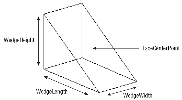
FaceCenterPoint The point at the center of the sloping face, which is also the center of the bounding box that encloses the wedge.
WedgeLength A positive value that represents the length of the wedge.
WedgeWidth A positive value that represents the width of the wedge.
WedgeHeight A positive value that represents the height of the wedge.
In the next series of steps, you enter the DrawWedge macro and run it. Figure 15.3 shows the Wedge solid generated by the macro.
Figure 15.3 Wedge drawn by the DrawWedge macro (Listing 15.4)
Exercise 15.1: Building the 3D Solids Application
1. Continuing with the same drawing, add the DrawWedge macro’s code (Listing 15.4) into the Code window for ThisDrawing.
2. Return to the AutoCAD window, choose Tools ^ Macro ^ Macros, and run the macro from the Macros dialog box.
3. Follow the prompts in the command line to enter the position and dimensions required.
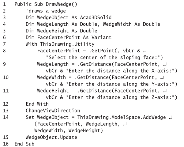
Listing 15.4: DrawWedge Macro
Analysis
• Line 1 starts the DrawWedge macro, which prompts the user to enter the information required and draws a Wedge solid to the specifications.
• Line 3 declares the WedgeObject variable that will be used to reference the 3DSolid object after the Wedge solid has been created.
• Lines 4 and 5 declare the variables used to represent the dimensions of the wedge in the x, y, and z directions.
• Line 6 declares the FaceCenterPoint variable as a Variant type so that it can be assigned a three-element array containing the point selected by the user for the center of the sloping face.
• Line 7 uses the With statement so that the GetPoint and GetDistance methods of the Utility object can be used without being fully qualified.
• Line 8 calls the GetPoint method to prompt the user to enter the center of the sloping face. This point is also the center of the bounding box for the Wedge object.
• Lines 9 through 11 prompt the user to enter the distances along the x-, y-, and z-axes to specify the size of the wedge.
• Line 12 ends the With statement.
• Line 13 calls the ChangeViewDirection macro that displays the Wedge solid at an angle, to make its shape more obvious.
• Line 14 calls the AddWedge method to create a Wedge solid and set up the WedgeObject variable to reference the 3DSolid object that is created to represent the wedge.
• Line 15 calls the Update method to redraw the Wedge object on the screen.
• Line 16 ends the DrawWedge macro.
Creating a Sphere
The AddSphere method is used to create a Sphere solid, given its center and radius. Listing 15.5 shows this method being called from the DrawSphere macro with the following variables as arguments:
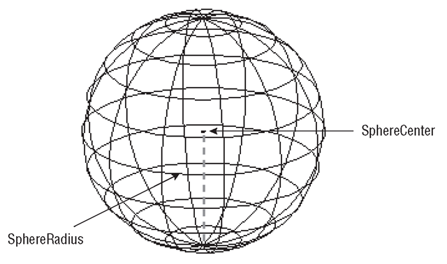
SphereCenter A three-element array representing the center of the sphere, which is also the center of the bounding box.
SphereRadius A positive value representing the radius of the sphere.
In the next series of steps, you enter the DrawSphere macro and run it. Figure 15.4 shows the Sphere solid drawn by the macro.
Figure 15.4 Sphere solid generated by the DrawSphere macro (Listing 15.5)
Exercise 15.1: Building the 3D Solids Application
1. Continuing with the same drawing, enter the DrawSphere macro’s code (Listing 15.5) into the Code window for ThisDrawing.
2. Return to the AutoCAD window, choose Tools ^ Macro ^ Macros, and run the macro from the Macros dialog box.
3. Follow the prompts in the command line to enter the sphere’s center and position.
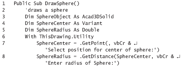
Listing 15.5: DrawSphere Macro
Analysis
• Line 1 starts the DrawSphere macro, which prompts the user to enter the center and radius, creates the sphere to the user’s specifications, and draws it on the screen.
• Line 3 declares the SphereObject variable as being capable of referencing a 3DSolid object.
• Line 4 declares the SphereCenter variable as a Variant type, so that the three-element array returned by the GetPoint method can be assigned to it in a single statement.
• Line 5 declares the Radius variable that determines the size of the sphere.
• Line 6 uses the With statement so that the Utility object’s GetPoint and GetDistance methods can be used without having to fully qualify them.
• Line 7 calls the GetPoint method to prompt the user to enter the center for the sphere solid. This point is also the center of the bounding box for this solid.
• Line 8 calls the GetDistance method to prompt the user for the length of the sphere’s radius.
• Line 10 updates the number of ContourLinesPerSurface property to 12. The number required for a reasonable image depends on the surface’s level of curvature and the screen area it covers. Since ContourLinesPerSurface is a property of the Preferences object of ThisDrawing, all the solids in the active drawing will be updated to reflect any new setting.
• Line 11 calls the AddSphere method to create a Sphere solid, and sets up the SphereObject variable as a reference to the 3DSolid object that represents the sphere.
• Line 12 calls the Update method to draw the sphere on the screen.
• Line 13 calls the ChangeViewDirection to view the sphere from a different direction.
• Line 14 ends the DrawSphere macro.
The Sphere is the only solid that doesn’t change its outline as the viewing direction changes.
