In this topic you’ll learn how to add three-dimensional solids to your drawings. AutoCAD provides a variety of methods for creating the kinds of primitive solids that are traditionally used in constructive solid geometry (CSG) techniques. You’ll see how to add these to your drawings from macros and view them from different directions. I’ll show you how to combine primitive solids to form complex solids, and some ways of creating other solids from planar surfaces using extrusion and revolution. Also covered are techniques for chamfering, filleting, and cross-sectioning from your VBA code.
• Creating 3D solids
• Constructing complex solids
• Creating solids by extrusion and revolution
• Chamfered and filleted edges
• Cross sections
AutoCAD has a generic type called Acad3DSolid that can represent any 3D solid object that you can add to a drawing using the methods AddBox, AddCone, AddCylinder, AddElliptical Cone, AddElliptical Cylinder, AddExtrudedSolid, AddExtrudedSolidAlong-Path, AddRevolvedSolid, AddSphere, AddTorus, and AddWedge. The Acad3DSolid type declares the solid object that it represents as a free-form surface capable of taking on any shape. Let’s take a look at a few of these 3D solids provided by AutoCAD—boxes, wedges, cones, cylinders, spheres, and tori—represented by the Acad3DSolid object type. These solids are typically used in traditional methods to construct complex solids—you’ll see how this is done later in the topic.
All the Acad3DSolids are positioned in the WCS by specifying the position of the centers of their bounding boxes. (A bounding box is the smallest box possible that completely encloses all the edges and vertices of a solid.) By default, these solids are all aligned in some way with the x-, y-, and z-axes.
The center of any solid object is the center of the imaginary bounding box that encloses it.
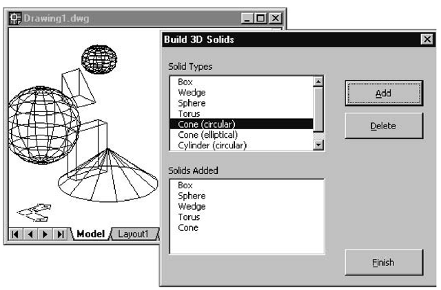
Exercise 15.1 continues through several sections, developing an application that allows you to add and delete simple solids in a new drawing. Figure 15.1 shows this application after five solids have been added to the Model Space.
Figure 15.1 The Build 3D Solids Application in action
Exercise 15.1: Building the 3D Solids Application
This exercise comprises a series of individual connected procedures that take you through drawing the various 3D solid objects provided by AutoCAD. You’ll start by creating the GUI.
1. Start a new project and add a UserForm.
2. Add two list boxes—one to show the types of solids available, and the other to show the solids added to the current drawing session. Figure 15.1 gives you an idea of how to position them.
3. Place a label above each list box to provide a description of its contents.
4. Create three command buttons: to add a solid, to delete a solid that has been added, and to finish running the application and return to the AutoCAD window.
5. Change the properties of the UserForm and the controls to those shown in Table 15.1.
Table 15.1 Properties for the Building 3D Solids Application
|
Old Name |
New Name |
Caption |
|
UserForm1 |
frmBuildSolids |
Build 3D Solids |
|
ListBoxI |
lslSolidTypes |
— |
|
ListBox2 |
lstSolidsAdded |
— |
|
Labell |
— |
Solid Types |
|
Label2 |
— |
Solids Added |
|
CommandButtonl |
cmdAdd |
Add |
|
CommandButton2 |
cmdDelete |
Delete |
|
CommandButton3 |
cmdFinish |
Finish |
6. Change the Accelerator property of cmdAdd to A, cmdDelete to D, and cmdFinish to F.
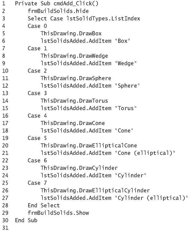
7. Enter the code for the event procedures ofthe GUI (Listing 15.1).
8. Enter the code for the ChangeViewDirection macro (Listing 15.2) into ThisDrawing’s Code window. The default view direction is along the z-axis, which means that solids may often appear two-dimensional (for example, a box may look like a rectangle). To emphasize that the solids are threedimensional, the ChangeViewDirection macro ensures that the solids are viewed from a different direction. This macro is called by all the macros in this exercise to emphasize the three-dimensional features of the solids being drawn.
Listing 15.1: Event Procedures of the Building 3D Solids Application
Analysis
• Line 1 starts the Click event procedure for the Add button, which adds the solid selected in the top list box to the Model Space and displays it in the bottom list box.
• Line 2 hides the UserForm so that the user can interact directly with the AutoCAD window to enter the details prompted for in the command line.
• Line 3 starts the Select Case statement that uses the ListIndex property to identify the selected item from the IstSolidTypes list box.
• Lines 4 through 6 contain the code that’s run when the Box item from the top list box is selected as the Add button is clicked. Line 5 calls the DrawBox procedure (Listing 15.3). Line 6 calls the AddItem method to add the string "Box" to the bottom list box,showing that the solid has been added and allowing the user to select it if they want to delete it.
• Lines 7 through 27 provide code similar to Lines 4 through 6, for the other solids from the top list.
• Line 28 ends the Select Case statement.
• Line 29 calls the Show method of the UserForm to display it to the user, allowing them to add the next solid or delete an existing one.
• Line 30 ends the cmdAdd_Click event procedure.
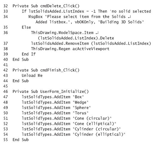
• Line 32 starts the Click event procedure for the Delete command button, which removes the solid selected in the bottom list box from the Model Space and from the bottom list box.
• Line 33 checks to see if a solid is selected in the bottom list box.
• Line 34 runs if no solid has been selected. It calls the MsgBox function to instruct the user to select an item from the bottom list box.
• Line 35 starts the Else part of the If statement block.
• Line 36 uses the Item property with the same index value as the selected item from the bottom list box (lstSolidsAdded.ListIndex), to identify the solid to be deleted from the Model Space. The solid is removed using the Delete method.
• Line 37 calls the RemoveItem method of the lstSolidsAdded listbox, supplying the position in the list of the selected item. This removes the item from the list and resets ListIndex to -1, so it is important that Line 36 is executed before this line.
• Line 38 calls the Regen method to redraw all the solids in the active viewport, to ensure that the deleted solid disappears immediately.
• Lines 39 and 40 end the If statement and the cmdDelete_Click event procedure, respectively.
• Line 42 starts the Click event procedure of the Finish command button.
• Line 43 uses the Unload statement with the Me keyword to unload the UserForm, thus closing the Building 3D Solids application.
• Line 44 ends the cmdFinish_Click event procedure.
• Line 46 starts the UserForm’s Initialize event procedure, which adds all the solid types to the top list box and clears any items from the bottom list box. The application assumes that the Model Space is completely empty when the application is executed, so that the position of the selected item from the bottom list box (ListIndex property) can be used to identify the corresponding object from the ModelSpace collection.
• Lines 47 through 54 use the AddItem method to add the names of the 3D solids to the top list box.
• Line 55 ends the UserForm_Initialize event procedure.
Listing 15.2: ChangeViewDirection Macro
Analysis
• Line 1 starts the ChangeViewDirection macro,which changes the viewing direction of the WCS.
• Line 2 declares ViewDirection as a three-element array.
• Lines 3 through 5 assign values to the three components that make up the view direction vector.
• Line 6 assigns the ViewDirection array to the Direction property of the active viewport.
• Line 7 assigns the active viewport to itself to regenerate the objects associated with it, in order to ensure that the changes made to the direction vector take effect on the drawing displayed on the screen.
Changes made to a Viewport object are not updated on the screen until that viewport is explicitly made the active viewport again.
• Line 8 ends the ChangeViewDirection macro.
Now let’s get started creating the different types of solids and incorporating them into the Building 3D Solids application.


