Setting the shortcut menu variable
Call the line tool, draw a few lines and then right-click. The right-click menu shown in Fig. 4.15 may well appear. A similar menu will also appear when any tool is called. Some operators prefer using this menu when constructing drawings. To stop this menu appearing:
And the menu will no longer appears when a tool is in action.
Fig. 4.15 The right-click menu
setting layers
1. At the command line enter layer or la followed by a right-click. The Layer Properties Manager palette appears (Fig. 4.16).
2. Click the New Layer icon. Layer1 appears in the layer list. Overwrite the name Layer1 entering Centre.
Fig. 4.16 The Layer Properties Manager palette
3. Repeat step 2 four times and make four more layers entitled Construction, Dimensions, Hidden and Text.
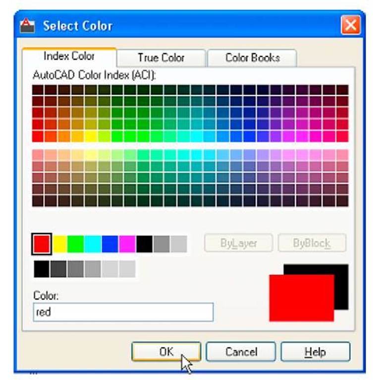
4. Click one of the squares under the Color column of the dialog. The Select Color dialog appears (Fig. 4.17). Double-click on one of the colours in the Index Color squares. The selected colour appears against the layer name in which the square was selected. Repeat until all five new layers have a colour.
Fig. 4.17 The Select Color dialog
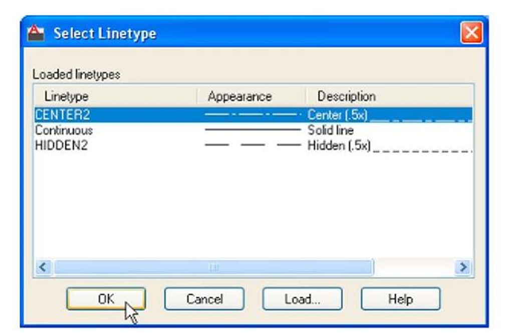
5. Click on the linetype Continuous against the layer name Centre. The Select Linetype dialog appears (Fig. 4.18). Click its Load… button and from the Load or Reload Linetypes dialog double-click CENTER2. The dialog disappears and the name appears in the Select Linetype dialog. Click the OK button and the linetype CENTER2 appears against the layer Center.
Fig. 4.18 The Select Line type dialog
6. Repeat with layer Hidden, load the linetype HIDDEN2 and make the linetype against this layer HIDDEN2.
7. Click on the any of the line weights in the Layer Properties Manager. This brings up the Lineweight dialog (Fig. 4.19). Select the lineweight 0.3. Repeat the same for all other layers. Then click the Close button of the Layer Properties Manager.
Fig. 4.19 The Line weight dialog
Saving the template file
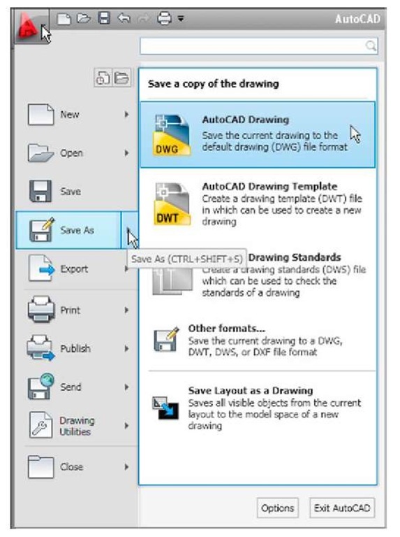
1. Left-click on Save As in the menu appearing with a left-click on the AutoCAD icon at the top left-hand corner of the screen ( ).
Fig. 4.20 Calling Save As
2. In the Save Drawing As dialog which comes on screen (Fig. 4.21), click the arrow to the right of the Files of type field and in the popup list associated with the field click on AutoCAD Drawing Template (*.dwt). The list of template files in the AutoCAD 2011/Template directory appears in the file list.
Fig. 4.21 Saving the template to the name acadiso.dwt
3. Click on acadiso in the file list, followed by a click on the Save button.
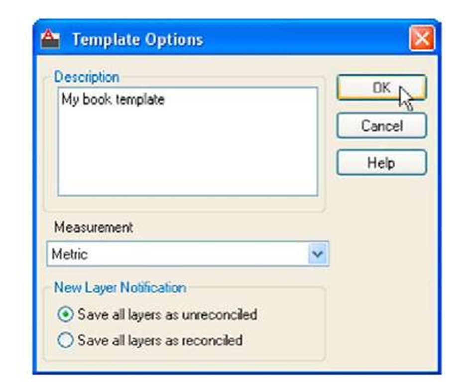
4. The Template Option dialog appears. Make entries as suggested in Fig. 4.22, making sure that Metric is chosen from the popup list. The template can now saved to be opened for the construction of drawings as needed. Now when AutoCAD 2011 is opened again the template acadiso.dwt appears on screen.
Fig. 4.22 The Template Description dialog
Note
Remember that if others are using the computer it is advisable to save the template to a name of your own choice.
Template file to include imperial dimensions
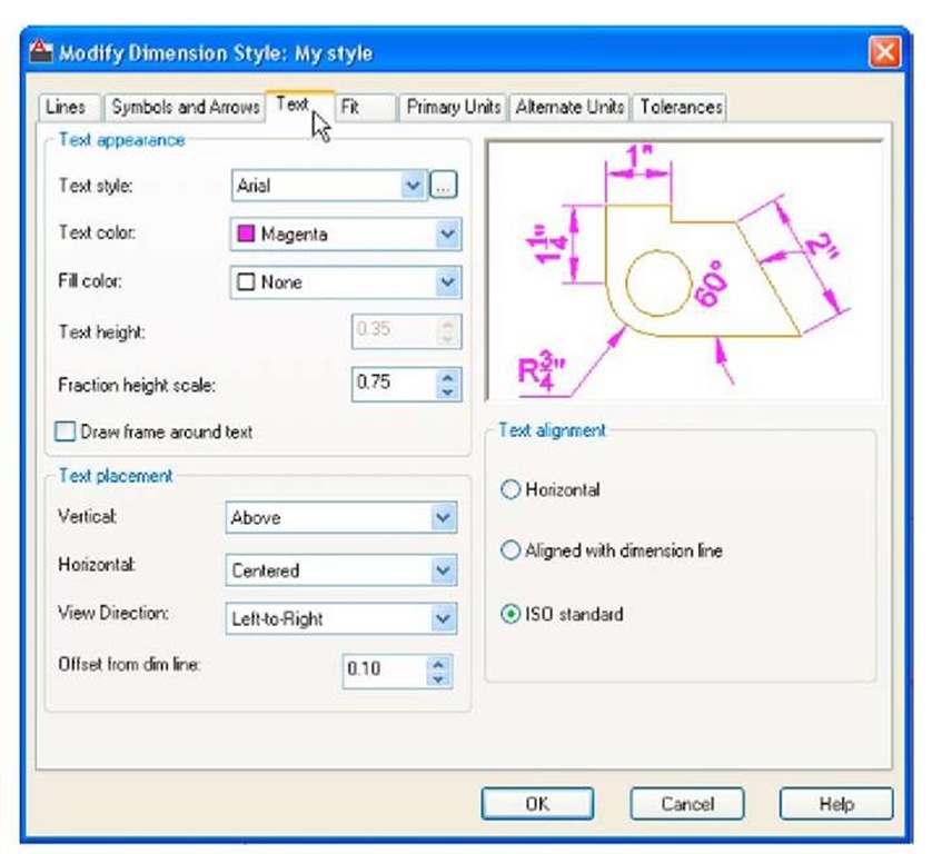
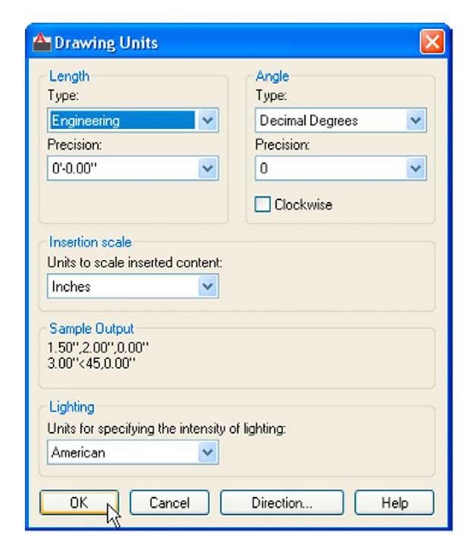
If dimensions are to be in Imperial measure - in yards, feet and inches, first set Limits to 28,18. In addition the settings in the Dimension Style Manager will need to be different from those shown earlier. Settings for Imperial measure in the Primary Units sub-dialog need to be set as shown in Fig. 4.23. Settings in the Text sub-dialog of the Text Style dialog also need to be set as shown in Fig. 4.24.
In addition the settings in the Primary Units dialog also need settings to be different to those for Metric dimensions as shown in Fig. 4.25.
Fig. 4.23 Settings for Imperial dimensions in Primary Units
Fig. 4.24 Settings for Imperial dimensions set in Text
Fig. 4.25 Settings for Imperial dimensions in the Primary Units dialog
REVISION NOTES
1. The Zoom tools are important in that they allow even the smallest parts of drawings to be examined, amended or modified.
2. The Zoom tools can be called from the sub-menu of the View drop-down menu, or by entering z or zoom at the command line. The easiest is to enter z at the command line.
3. There are five methods of calling tools for use – selecting a tool icon in a panel from a group of panels in the Ribbon; entering the name of a tool in full at the command line; entering an abbreviation for a tool; selecting a tool from a drop-down menu. If working in the AutoCAD Classic workspace, tools are called from toolbars.
4. When constructing large drawings, the Pan tool and the Aerial View window allow work to be carried out in any part of a drawing, while showing the whole drawing in the Aerial View window.
5. An A3 sheet of paper is 420 mm by 297 mm. If a drawing constructed in the template acadiso.dwt described in this topic, is printed/plotted full size (scale 1:1), each unit in the drawing will be 1 mm in the print/plot.
6. When limits are set it is essential to call Zoom followed by a (All) to ensure that the limits of the drawing area are as set.
7. If the right-click menu appears when using tools, the menu can be aborted if required by setting the SHORTCUTMENU variable to 0.


