Drawing templates
In topics 1-3, drawings were constructed in the template acadiso.dwt which loaded when AutoCAD 2011 was opened. The default acadiso template has been amended to Limits set to 420,297 (coordinates within which a drawing can be constructed), Grid Display set to 10, Snap Mode set to 5 and the drawing area Zoomed to All.
Throughout this topic most drawings will be based on an A3 sheet, which measures 420 units by 297 units (the same as Limits).
Note
As mentioned before if others are using the computer on which drawings are being constructed, it is as well to save the template being used to another file name, or if thought necessary to a memory stick or other temporary type of disk.
Adding features to the template
Four other features will now be added to our template:
Text style – set in the Text Style dialog.
Dimension style – set in the Dimension Style Manager dialog.
Shortcut menu variable – set to 0.
Layers – set in the Layer Properties Manager dialog.
Setting text
1. At the command line:
1. At the command line:
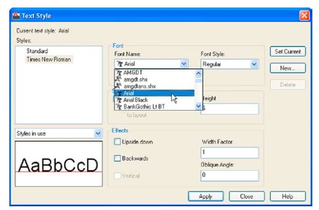
2. The Text style dialog appears (Fig. 4.8). In the dialog, enter 6 in the Height field. Then left-click on Arial in the Font name popup list. Arial font letters appear in the Preview area of the dialog.
Fig. 4.8 The Text Style dialog
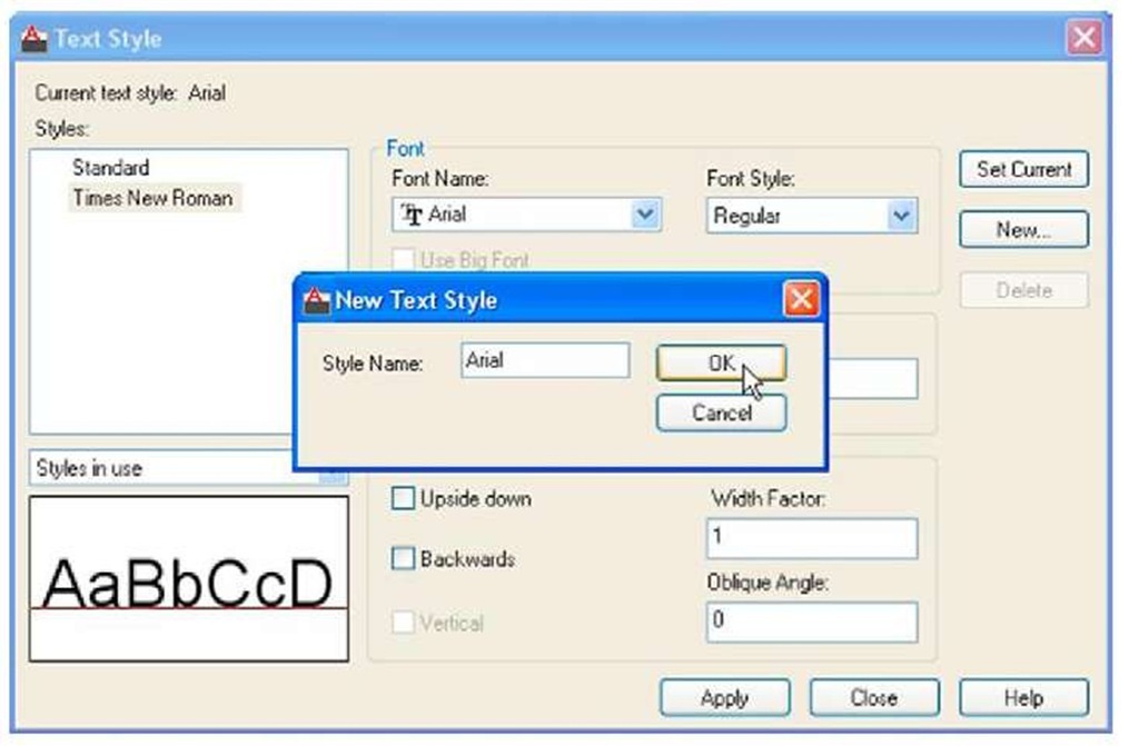
3. Left-click the New button and enter Arial in the New text style subdialog which appears (Fig. 4.9) and click the OK button.
4. Left-click the Set Current button of the Text Style dialog.
5. Left-click the Close button of the dialog.
Fig. 4.9 The New Text Style sub-dialog
Setting dimension style
Settings for dimensions require making entries in a number of sub-dialogs in the Dimension Style Manager. To set the dimensions style:
1. At the command line:
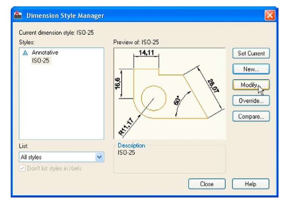
And the Dimensions Style Manager dialog appears (Fig. 4.10).
Fig. 4.10 The Dimensions Style Manager dialog
2. In the dialog, click the Modify… button.
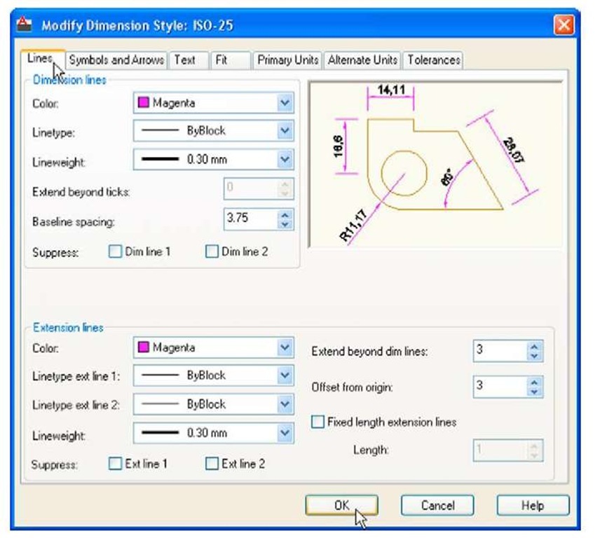
3. The Modify Dimension Style dialog appears (Fig. 4.11). This dialog shows a number of tabs at the top of the dialog. Click the Lines tab and make settings as shown in Fig. 4.11. Then click the OK button of that dialog.
Fig. 4.11 The setting for Lines in the Modify Dimensions Style dialog
4. The original Dimension Style Manager reappears. Click its Modify button again.
5. The Modify Dimension Style dialog reappears (Fig. 4.12), click the Symbols and Arrows tab. Set Arrow size to 6.
6. Then click the Text tab. Set Text style to Arial, set Color to Magenta, set Text Height to 6 and click the ISO check box in the bottom right-hand corner of the dialog.
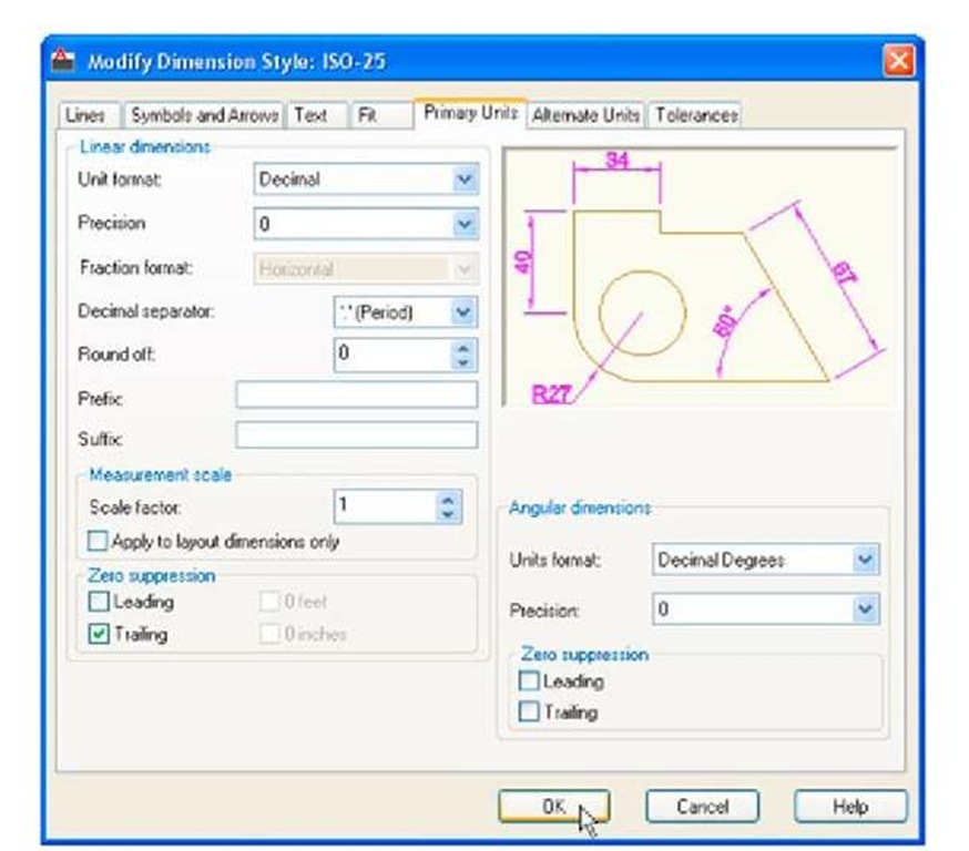
7. Then click the Primary Units tab and set the units Precision to 0, that is no units after decimal point and Decimal separator to Period. Click the sub-dialogs OK button (Fig. 4.12).
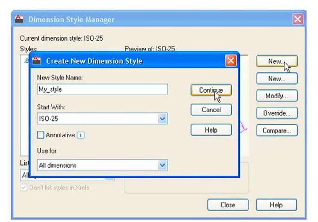
8. The Dimension Styles Manager dialog reappears showing dimensions, as they will appear in a drawing, in the Preview of my-style box. Click the New. button. The Create New Dimension Style dialog appears (Fig. 4.13).
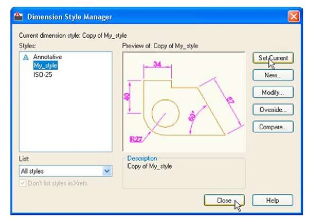
9. Enter a suitable name in the New Style Name: field – in this example this is My-style. Click the Continue button and the Dimension Style Manager appears (Fig. 4.14). This dialog now shows a preview of the My-style dimensions. Click the dialog’s Set Current button, following by another click on the Close button. See Fig. 4.14.
Fig. 4.12 Setting Primary Units in the Dimension Style Manager
Fig. 4.13 The Create New Dimension Style dialog
Fig. 4.14 The Dimension Style Manager reappears. Click the Set Current and Close buttons
