The Stretch tool
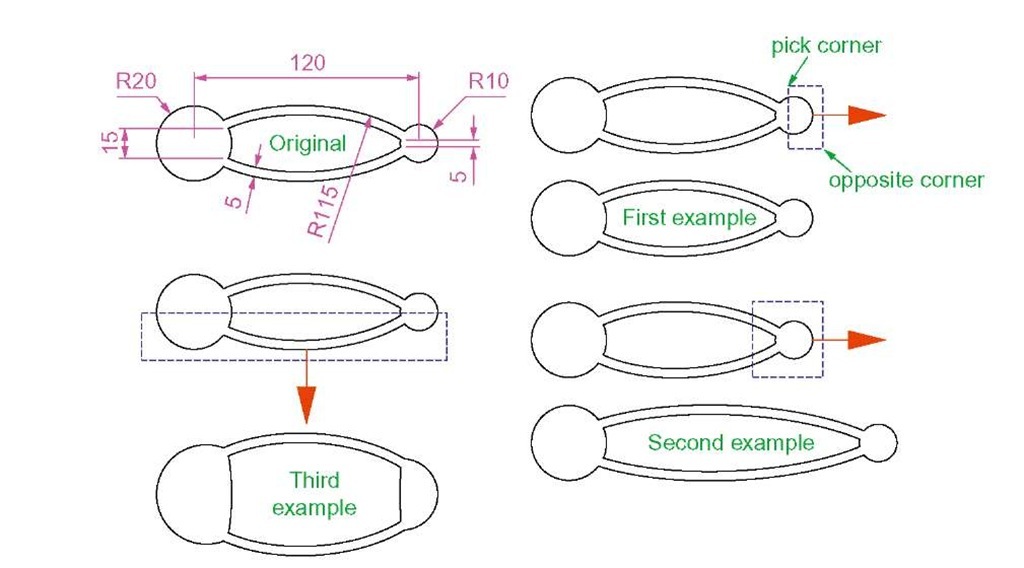
Examples – Stretch (Fig. 5.34)
As its name implies the Stretch tool is for stretching drawings or parts of drawings. The action of the tool prevents it from altering the shape of circles in any way. Only crossing or polygonal windows can be used to determine the part of a drawing which is to be stretched.
1. Construct the drawing labelled Original in Fig. 5.34, but do not include the dimensions. Use the Circle, Arc, Trim and Polyline Edit tools. The resulting outlines are plines of width = 1. With the Copy tool make two copies of the drawing.
Note
In each of the three examples in Fig. 5.34, the broken lines represent the crossing windows required when Stretch is used.
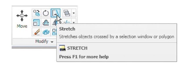
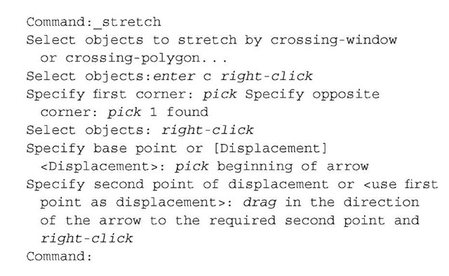
2. Call the Stretch tool - either click on its tool icon in the Home/Modify panel (Fig. 5.33), pick its name in the Modify drop-down menu or enter s or stretch at the command line, which shows.
Fig. 5.33 The Stretch tool icon from the Home/Modify panel
Fig. 5.34 Examples – Stretch
Notes
1. When circles are windowed with the crossing window no stretching can take place. This is why, in the case of the first example in Fig. 5.33, when the second point of displacement was picked, there was no result – the outline did not stretch.
2. Care must be taken when using this tool as unwanted stretching can occur (Fig. 5.34).
The Break tool
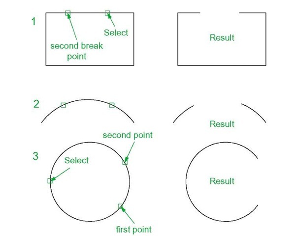
Examples – Break (Fig. 5.36)
1. Construct the rectangle, arc and circle (Fig. 5.36).
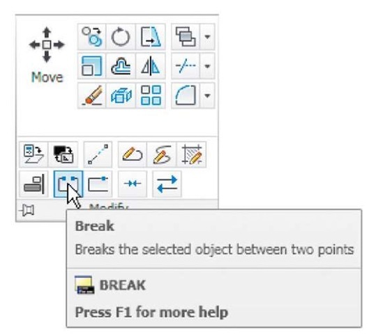
2. Call Break - either click on its tool icon in the Home/Modify panel (Fig. 5.35), click Break in the Modify drop-down menu or enter br or break at the command line, which shows:
For drawings 1 and 2
Fig. 5.35 The Break tool icon from the Home/Modify panel For drawing 3
The results are shown in Fig. 5.36.
Fig. 5.36 Examples – Chamfer
Note
Remember the default rotation of AutoCAD 2011 is counterclockwise. This applies to the use of the Break tool.
The Join tool
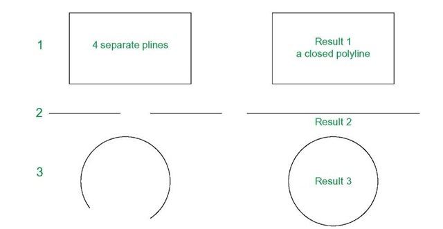
The Join tool can be used to join plines providing their ends are touching, to join lines which are in line with each other, and to join arcs and convert arcs to circles.
Examples – Join (Fig. 5.38)
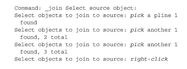
1. Construct a rectangle from four separate plines – drawing 1 of Fig. 5.38; construct two lines – drawing 2 of Fig. 5.38 and an arc -drawing 3 of Fig. 5.38.
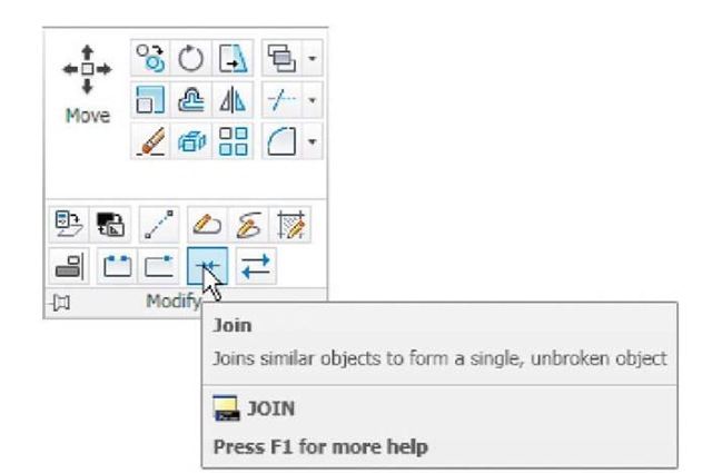
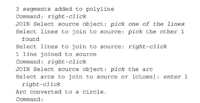
2. Call the Join tool - either click the Join tool icon in the Home/Modify panel (Fig. 5.37), select Join from the Modify drop-down menu or enter join or j at the command line. The command line shows:
Fig. 5.37 The Join tool icon from the Home/Modify panel
The results are shown in Fig. 5.38.
Fig. 5.38 Examples – Join
