The Move tool
Example – Move (Fig. 5.25)
1. Construct the drawing Fig. 5.23.
Fig. 5.23 Example – Move – drawing
2. Call Move – click the Move tool icon in the Home/Modify panel (Fig. 5.24), pick Move from the Modify drop-down menu or enter m or move at the command line, which shows:
Fig. 5.24 The Move tool from the Home/Modify panel
The result is given in Fig. 5.25.
Fig. 5.25 Example – Move
The Rotate tool
When using the Rotate tool remember the default rotation of objects within AutoCAD 2011 is counterclockwise (anticlockwise).
Example – Rotate (Fig. 5.27)
1. Construct drawing 1 of Fig. 5.27 with Polyline. Copy the drawing 1 three times (Fig. 5.27).
2. Call Rotate – left-click on its tool icon in the Home/Modify panel (Fig. 5.26), pick Rotate from the Modify drop-down menu or enter ro or rotate at the command line. The command line shows: and the first copy rotates through the specified angle.
Fig. 5.26 The Rotate tool icon from the Home/Modify panel
3. Repeat for drawings 3 and 4 rotating as shown in Fig. 5.27.
Fig. 5.27 Example – Rotate
The Scale tool
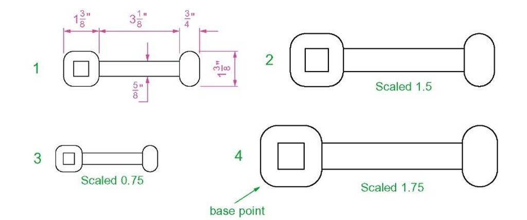
Examples – Scale (Fig. 5.29)
1. Using the Rectangle and Polyline tools, construct drawing 1 of Fig. 5.29. The Rectangle fillets are R10. The line width of all parts is 1. Copy the drawing 3 times to give drawings 2, 3 and 4.
2. Call Scale - left-click on its tool icon in the Home/Draw panel (Fig. 5.28), pick Scale from the Modify drop-down-menu or enter sc or scale at the command line which then shows:
Fig. 5.28 The Scale tool from the Home/Modify panel
3. Repeat for the other two drawings 3 and 4 scaling to the scales given with the drawings.
The results are shown in Fig. 5.29.
Fig. 5.29 Examples – Scale
The Trim tool
This tool is one which will be frequent use when constructing drawings.
First example – Trim (Fig. 5.31)
1. Construct the drawing Original drawing in Fig. 5.31.
2. Call Trim - either left-click on its tool icon in the Home/Modify panel (Fig. 5.30), pick Trim from the Modify drop-down menu or enter tr or trim at the command line, which then shows:
Fig. 5.30 The Trim tool icon from the Home/Modify panel
3. This completes the First stage as shown in Fig. 5.31. Repeat the Trim sequence for the Second stage.
4. The Third stage drawing of Fig. 5.31 shows the result of the trims at the left-hand end of the drawing.
5. Repeat for the right-hand end. The final result is shown in the drawing labelled Result in Fig. 5.31.
Fig. 5.31 First example – Trim
Second example – Trim (Fig. 5.32)
1. Construct the left-hand drawing of Fig. 5.32.
2. Call Trim. The command line shows:
3. Repeat for the other required trims. The result is given in Fig. 5.32.
Fig. 5.32 Second example – Trim


