Undo and Redo tools
Two other tools of value when errors have been made are the Undo and Redo tools. To undo any last action when constructing a drawing, either left-click the Undo tool in the Quick Access toolbar (Fig. 2.20) or enter u at the command line. No matter which method is adopted the error is deleted from the drawing.
Fig. 2.20 The Undo tool in the Quick Access toolbar
Everything constructed during a session of drawing can be undone by repeated clicking on the Undo tool icon or by repeatedly entering u’s at the command line.
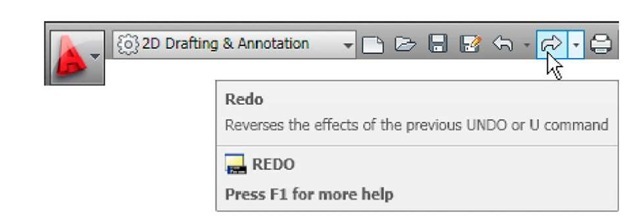
To bring back objects that have just been removed by the use of Undo’s, left-click the Redo tool icon in the Quick Access toolbar (Fig. 2.21) or enter redo at the command line.
Fig. 2.21 The Redo tool icon in the Quick Access toolbar
Drawing with the polyline tool
When drawing lines with the Line tool, each line drawn is an object. A rectangle drawn with the Line tool is four objects. A rectangle drawn with the Polyline tool is a single object. Lines of different thickness, arcs, arrows and circles can all be drawn using this tool. Constructions resulting from using the tool are known as polylines or plines. The tool can be called from the Home/Draw panel (Fig. 2.22) or by entering pl at the command line.
Fig. 2.22 The Polyline tool icon in the Home/Draw panel
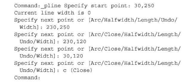
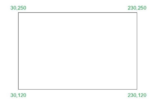
First example – Polyline tool (Fig. 2.23)
In this example enter and right-click have not been included (Fig. 2.23). Left-click the Polyline tool icon. The command line shows:
Fig. 2.23 First example – Polyline tool
Notes
1. Note the prompts - Arc for constructing pline arcs, Close to close an outline, Halfwidth to halve the width of a wide pline, Length to enter the required length of a pline, Undo to undo the last pline constructed Width to change the width of the pline.
2. Only the capital letter(s) of a prompt needs to be entered in upper or lower case to make that prompt effective.
3. Other prompts will appear when the Polyline tool is in use as will be shown in later examples.
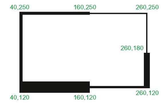
Second example – Polyline tool (Fig. 2.24)
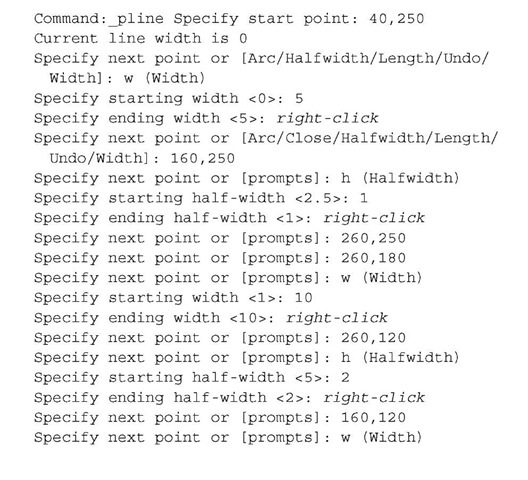
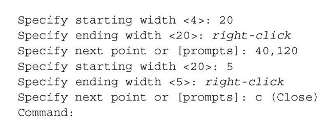
This will be a long sequence, but it is typical of a reasonably complex drawing using the Polyline tool. In the following sequences, when a prompt line is to be repeated, the prompts in square brackets ([]) will be replaced by [prompts] (Fig. 2.24).
Fig. 2.24 Second example – Polyline tool
Left-click the Polyline tool icon. The command line shows:
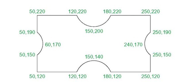
Third example – Polyline tool (Fig. 2.25)
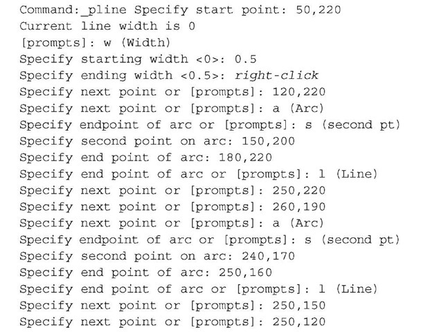
Left-click the Polyline tool icon. The command line shows:
And so on until the outline Fig. 2.25 is completed.
Fig. 2.25 Third example – Polyline tool
Fourth example – Polyline tool (Fig. 2.26)
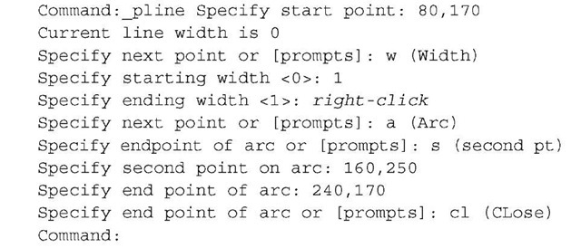
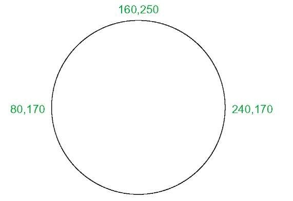
Left-click the Polyline tool icon. The command line shows:
And the circle Fig. 2.26 is formed.
Fig. 2.26 Fourth example – Polyline tool
Fifth example – Polyline tool (Fig. 2.27)
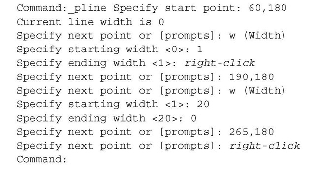
Left-click the Polyline tool icon. The command line shows:
And the arrow Fig. 2.27 is formed.
Fig. 2.27 Fifth example – Polyline tool
REVISION NOTES
1. The following terms have been used in this topic:
Left-click - press the left-hand button of the mouse.
Click - same meaning as left-click.
Double-click – press the left-hand button of the mouse twice.
Right-click – press the right-hand button of the mouse – has the same result as pressing the Return key of the keyboard.
Drag - move the cursor on to a feature, and holding down the left-hand button of the mouse pull the object to a new position. Only applies to features such as dialogs and palettes, not to parts of drawings.
Enter - type the letters of numbers which follow at the keyboard.
Pick - move the cursor on to an item on screen and press the left-hand button of the mouse.
Return – press the Enter key of the keyboard. This key may also marked with a left facing arrow. In most cases (but not always) has the same result as a right-click.
Dialog - a window appearing in the AutoCAD window in which settings may be made.
Drop-down menu – a menu appearing when one of the names in the menu bar is clicked.
Tooltip - the name of a tool appearing when the cursor is placed over a tool icon.
Prompts - text appearing in the command window when a tool is selected, which advise the operator as to which operation is required.
2. Three methods of coordinate entry have been used in this topic:
Absolute method – the coordinates of points on an outline are entered at the command line in response to prompts.
Relative method - the distances in coordinate units are entered preceded by @ from the last point which has been determined on an outline. Angles, which are measured in a counterclockwise direction, are preceded by <.
Tracking - the rubber band of the line is dragged in the direction in which the line is to be drawn and its distance in units is entered at the command line followed by a right-click.
Line and Polyline tools - an outline drawn using the Line tool consists of a number of objects – the number of lines in the outline. An outline drawn using the Polyline is a single object.

