Drawing with the Circle tool
First example – Circle tool (Fig. 2.13)
1. Close the drawing just completed and open the acadiso.dwt template.
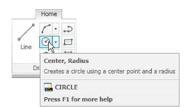
2. Left-click on the Circle tool icon in the Home/Draw panel (Fig. 2.11).
Fig. 2.11 The Circle tool from the Home/Draw panel
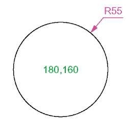
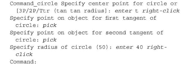
3. Enter a coordinate and a radius against the prompts appearing in the command window as shown in Fig. 2.12, followed by right-clicks. The circle (Fig. 2.13) appears on screen.
Fig. 2.12 First example – Circle. The command line prompts when Circle is called
Fig. 2.13 First example – Circle tool
Second example – Circle tool (Fig. 2.15)
1. Close the drawing and open the acadiso.dwt screen.
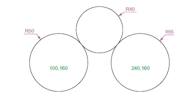
2. Left-click on the Circle tool icon and construct two circles as shown in the drawing Fig. 2.14 in the positions and radii shown in Fig. 2.15.
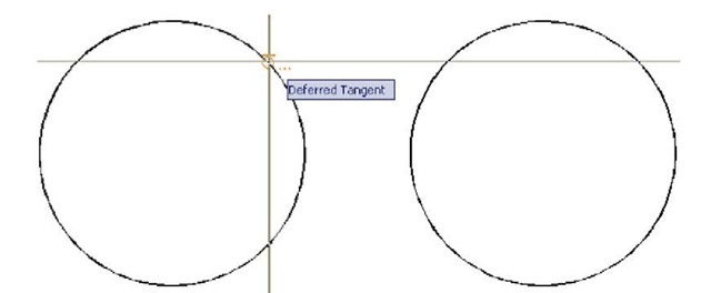
Fig. 2.14 Second example – Circle tool – the two circles of radius 50
Fig. 2.15 Second example
3. Click the Circle tool again and against the first prompt enter t (the abbreviation for the prompt tan tan radius), followed by a right-click.
The circle of radius 40 tangential to the two circles already drawn then appears (Fig. 2.15).
Notes
1. When a point on either circle is picked a tip (Deferred Tangent) appears. This tip will only appear when the Object Snap button is set on with a click on its button in the status bar, or the F3 key of the keyboard is pressed.
2. Circles can be drawn through 3 points or through 2 points entered at the command line in response to prompts brought to the command line by using 3P and 2P in answer to the circle command line prompts.
The Erase tool
If an error has been made when using any of the AutoCAD 2011 tools, the object or objects which have been incorrectly drawn can be deleted with the Erase tool. The Erase tool icon can be selected from the Home/ Modify panel (Fig. 2.16) or by entering e at the command line.
Fig. 2.16 The Erase tool icon from the Home/Modify panel
First example – Erase (Fig. 2.18)
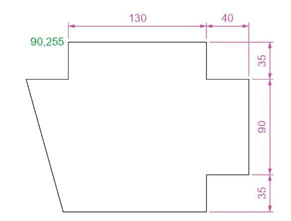
1. With Line construct the outline Fig. 2.17.
Fig. 2.17 First example – Erase. An incorrect outline
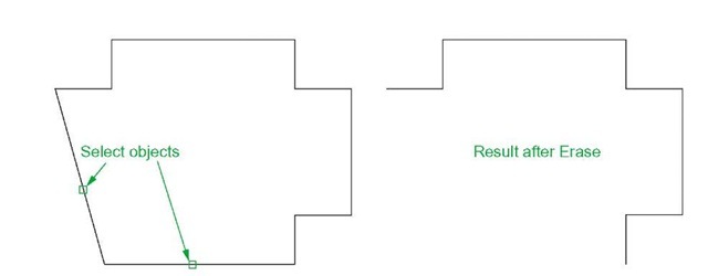
2. Assuming two lines of the outline have been incorrectly drawn, left-click the Erase tool icon. The command line shows:
And the two lines are deleted (right-hand drawing of Fig. 2.18).
Fig. 2.18 First example – Erase
Second example – Erase (Fig. 2.19)
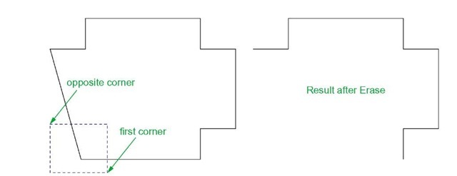
The two lines could also have been deleted by the following method: 1. Left-click the Erase tool icon. The command line shows:
And the two lines are deleted as in the right-hand drawing Fig. 2.19.
Fig. 2.19 Second example – Erase
