Why use Dynamic input?
Some operators may prefer constructing drawings without having to make entries at the command line in response to tool prompts. By using DYN drawings, whether in 2D or in 3D format, can be constructed purely from operating and moving the mouse, entering coordinates at the command line and pressing the down key of the keyboard when necessary.
Examples of using other Draw tools
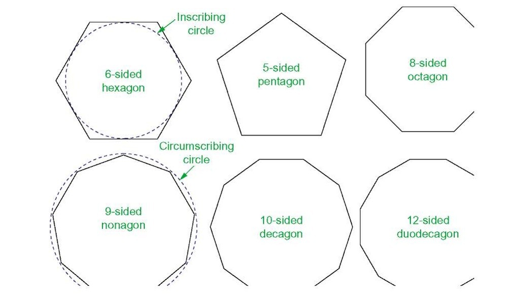
Polygon tool (Fig. 3.37)
Call the Polygon tool – either with a click on its tool icon in the Home/ Draw panel (Fig. 3.1), from the Draw drop-down menu, or by entering pol or polygon at the command line. No matter how the tool is called, the command line shows:
1. In the same manner construct a 5-sided polygon of centre 200,210 and of radius 60.
2. Then, construct an 8-sided polygon of centre 330,210 and radius 60.
3. Repeat to construct a 9-sided polygon circumscribed about a circle of radius 60 and centre 60,80.
4. Construct yet another polygon with 10 sides of radius 60 and of centre 200,80.
5. Finally another polygon circumscribing a circle of radius 60, of centre 330,80 and sides 12.
The result is shown in Fig. 3.37.
Fig. 3.37 First example – Polygon tool
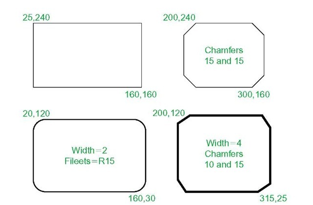
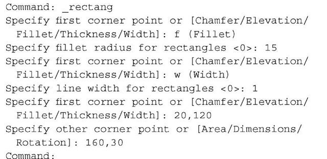
Rectangle tool – first example (Fig. 3.39)
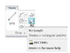
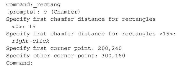
Call the Rectangle tool - either with a click on its tool icon in the Home/ Draw panel (Fig. 3.38) by entering rec or rectangle at the command line. The tool can be also called from the Draw drop-down menu. The command line shows (Fig. 3.39):
Fig. 3.38 The Rectangle tool from the Home/Draw panel
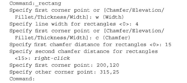
Fig. 3.39 Examples – Rectangle tool
Rectangle tool – second example (Fig. 3.39)
Rectangle tool – third example (Fig. 3.39)
Rectangle – fourth example (Fig. 3.39)
The polyline edit tool
The Polyline Edit tool is a valuable tool for the editing of polylines.
First example – Polyline Edit (Fig. 3.42)
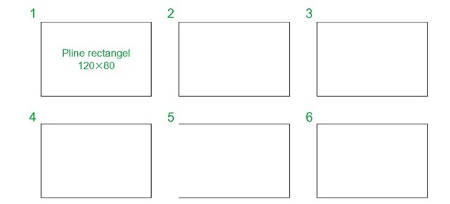
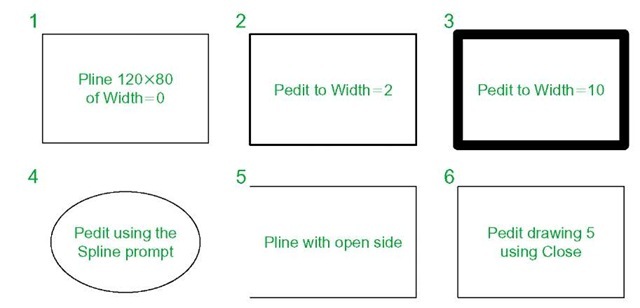
1. With the Polyline tool construct the outlines 1 to 6 of Fig. 3.40.
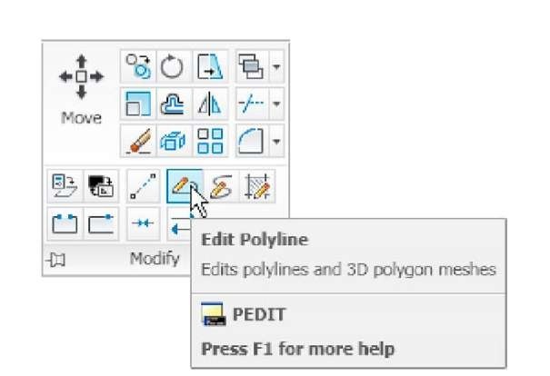
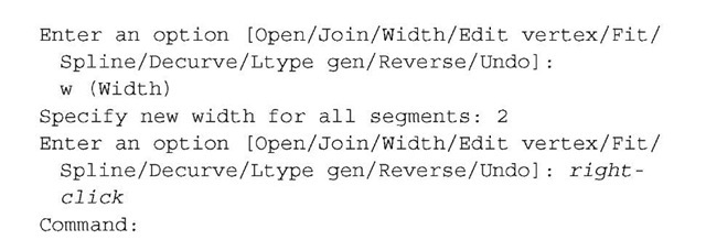
2. Call the Edit Polyline tool either from the Home/Modify panel (Fig. 3.41) or from the Modify drop-down menu, or by entering pe or pedit at the command line, which then shows:
Fig. 3.40 Examples – Edit Polyline – the plines to be edited
Fig. 3.41 Calling Edit Polyline from the Home/Modify panel
3. Repeat with pline 3 and pedit to Width = 10.
4. Repeat with line 4 and enter s (Spline) in response to the prompt line:
5. Repeat with pline 5 and enter j in response to the prompt line:
The result is shown in pline 6.
The resulting examples are shown in Fig. 3.42.
Fig. 3.42 Examples – Polyline Edit
Example – Multiple Polyline Edit (Fig. 3.43)
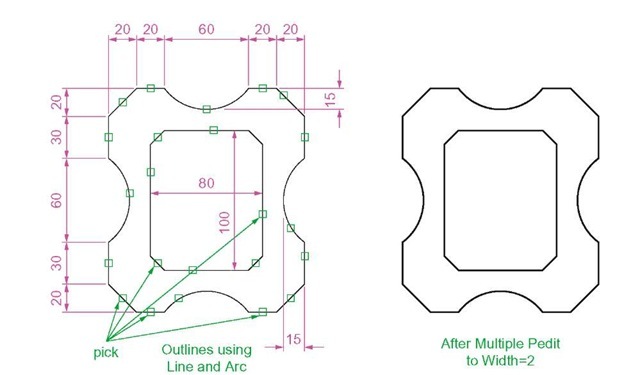
1. With the Polyline tool construct the left-hand outlines of Fig. 3.43.
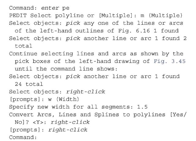
2. Call the Edit Polyline tool. The command line shows:
Fig. 3.43 Example – Multiple Polyline Edit
The result is shown in the right-hand drawing of Fig. 3.43.
Transparent commands
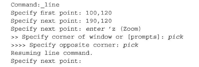
When any tool is in operation it can be interrupted by prefixing the interrupting command with an apostrophe (‘). This is particularly useful when wishing to zoom when constructing a drawing. As an example when the Line tool is being used:
And so on. The transparent command method can be used with any tool.
The set variable PELLIPSE
Many of the operations performed in AutoCAD are carried out under settings of SET VARIABLES.The variable PELLIPSE controls whether ellipses are drawn as splines or as polylines. It is set as follows:
And now when ellipses are drawn they are plines. If the variable is set to 0, the ellipses will be splines. The value of changing ellipses to plines is that they can then be edited using the Polyline Edit tool.
REVISION NOTES
The following terms have been used in this topic:
Field - a part of a window or of a dialog in which numbers or letters are entered or which can be read.
Popup list - a list brought in screen with a click on the arrow often found at the right-hand end of a field.
Object - a part of a drawing which can be treated as a single object. For example, a line constructed with the Line tool is an object, a rectangle constructed with the Polyline tool is an object and an arc constructed with the Arc tool is an object.
Ribbon palettes – when working in either of the 2D Drafting and Annotation or of the 3D Modeling workspace, tool icons are held in panels in the Ribbon.
Command line – a line in the command palette which commences with the word Command.
Snap Mode, Grid Display and Object Snap can be toggled with clicks on their respective buttons in the status bar. These functions can also be set with function keys: Snap Mode -F9, Grid Display – F7 and Object Snap – F3.
Object Snaps ensure accurate positioning of objects in drawings.
Object Snap abbreviations can be used at the command line rather than setting in ON in the Drafting Settings dialog.
Dynamic input allows constructions in any of the three AutoCAD 2011 workspaces or in a full screen workspace, without having to use the command palette for entering the initials of command line prompts.
Notes
There are two types of tooltip. When the cursor under mouse control is paced over a tool icon, the first (a smaller) tooltip is seen. If the cursor is held in position for a short time the second (a larger) tooltip is seen. Settings for the tooltip may be made in the Options dialog.
Polygons constructed with the Polygon tool are regular polygons – the edges of the polygons are all the same length and the angles are of the same degrees.
Polygons constructed with the Polygon tool are plines, so can be edited by using the Edit Polyline tool.
The easiest method of calling the Edit Polyline tool is to enter pe at the command line.
The Multiple prompt of the pedit tool saves considerable time when editing a number of objects in a drawing.
Transparent commands can be used to interrupt tools in operation by preceding the interrupting tool name with an apostrophe (‘).
Ellipses drawn when the variable PELLIPSE is set to 0 are splines; when PELLIPSE is set to 1, ellipses are polylines. When ellipses are in polyline form they can be modified using the pedit tool.

