Notes on the use of Dynamic Input
Although Dynamic Input can be used in any of the AutoCAD 2011 workspaces, some operators may prefer a larger working area. To achieve this a click on the Clean Screen icon in the bottom right-hand corner of the AutoCAD 2011 window produces an uncluttered workspace area. The command palette can be cleared from screen by entering command line hide at the command line. To bring it back press the keys Ctrl+9. These two operations produce a screen showing only title and status bars (Fig. 3.17). Some operators may well prefer working in such a larger than normal workspace.
Dynamic Input settings are made in the Dynamic Input sub-dialog of the Drafting Settings dialog (Fig. 3.18), brought to screen by entering os (or ds) at the command line.
Fig. 3.17 Example of using DYN in a clear screen
Fig. 3.18 Settings for DYN can be made in the Drafting Settings dialog
When Dynamic Input is in action, tools can be called by using any of the methods described.
1. By entering the name of the tool at the command line.
2. By entering the abbreviation for a tool name at the command line.
3. By selecting the tool’s icon from a panel.
4. By selecting the tool’s name from a drop-down menu.
When Dynamic Input is active and a tool is called, command prompts appear in a tooltip at the cursor position. Fig. 3.19 shows the tooltip appearing at the cursor position when the Line tool icon in the Home/ Draw panel is clicked.
Fig. 3.19 The prompt appearing on screen when the Line tool is selected
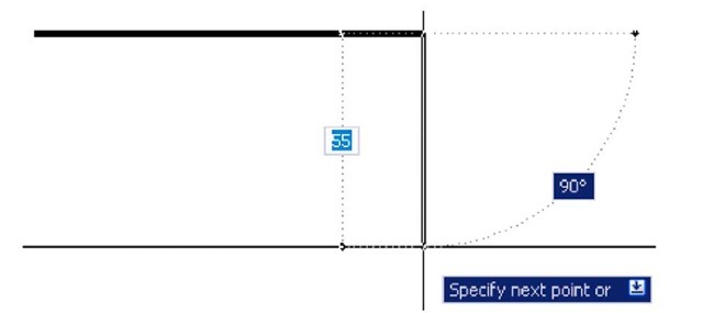
To commence drawing a line, either move the cursor under mouse control to the desired coordinate point and left-click as in Fig. 3.20, or enter the required x,y coordinates at the keyboard (Fig. 3.21) and left-click. To continue drawing with Line drag the cursor to a new position and either left-click at the position when the coordinates appear as required (Fig. 3.21), or enter a required length at the keyboard, which appears in the length box followed by a left-click (Fig. 3.22).
Fig. 3.20 Drag the cursor to the required point and left-click
Fig. 3.21 Enter coordinates for the next point and left-click
Fig. 3.22 Enter length at keyboard and right-click
When using Dynamic Input the selection of a prompt can be made by pressing the down key of the keyboard (Fig. 3.23) which causes a popup menu to appear. A click on the required prompt in such a popup menu will make that prompt active.
Dynamic Input – first example – Polyline
1. Select Polyline from the Home/Draw panel (Fig. 3.24).
2. To start the construction click at any point on screen. The prompt for the polyline appears with the coordinates of the selected point showing. Left-click to start the drawing (Fig. 3.25).
Fig. 3.23 The down key of the keyboard
Fig. 3.24 Selecting Polyline from the Home/Draw panel
Fig. 3.25 Dynamic Input – first example – Polyline – the first prompt
3. Move the cursor and press the down key of the keyboard. A popup menu appears from which a prompt selection can be made. In the menu click Width (Fig. 3.26).
4. Another prompt field appears. At the keyboard enter the required width and right-click. Then left-click and enter ending width or right-click if the ending width is the same as the starting width (Fig. 3.27).
5. Drag the cursor to the right until the dimension shows the required horizontal length and left-click (Fig. 3.28).
6. Drag the cursor down until the vertical distance shows and left-click (Fig. 3.29).
7. Drag the cursor to the left until the required horizontal distance is showing and right-click (Fig. 3.30).
8. Press the down key of the keyboard and click Close in the menu (Fig. 3.31). The rectangle completes.
Fig. 3.26 Dynamic Input – first example – Polyline – click Width in the popup menu
Fig. 3.27 Dynamic Input – first example – Polyline – entering widths
Fig. 3.28 Dynamic Input – first example – Polyline – the horizontal length
Fig. 3.29 Dynamic Input – first example – Polyline – the vertical height
Fig. 3.30 Dynamic Input – first example – Polyline – the horizontal distance
Fig. 3.31 Dynamic Input – first example – Polyline – selecting Close from the popup menu Fig. 3.32 shows the completed drawing. DYN – second example – Zoom
1. Enter Zoom or z at the command line. The first Zoom prompt appears (Fig. 3.33).
Fig. 3.32 Dynamic Input – first example – Polyline
Fig. 3.33 Dynamic Input – second example – Zoom – enter Zoom at the command line. The prompts which then appear
2. Right-click and press the down button of the keyboard. The popup list (Fig. 3.34) appears from which a Zoom prompt can be selected.
3. Carry on using the Zoom tool as described in topic 4.
Fig. 3.34 Dynamic Input – second example – Zoom – the popup menu appearing with a right-click and pressing the down keyboard button
DYN – third example – dimensioning
When using DYN, tools can equally as well be selected from a panel. Fig. 3.35 shows the Linear tool from the Home/Annotation panel selected when dimensioning a drawing.
Fig. 3.35 Selecting Linear from the Home/Annotation panel
A prompt appears asking for the first point. Move the cursor to the second point, another prompt appears (Fig. 3.36). Press the down button of the keyboard and the popup list (Fig. 3.36) appears from which a selection can be made.
Fig. 3.36 Dynamic Input – third example – dimensioning – the popup menu associated with Linear dimensioning
The Dynamic Input method of constructing 2D drawings can equally as well be used when constructing 3D solid models drawings.


