Most cars built after 1975 have electronic ignition systems that require no regular servicing. Some have no distributors at all. All testing and servicing of these systems should be left to trained professionals because they are easily damaged if hooked up improperly, and they employ high voltage that can also damage you.
If your car has an electronic ignition system, the only work you can do is to replace the distributor cap and rotor if they become damaged. However, even if you have a distributorless system, don’t forget to read and change your spark plugs and check that your cables and connections haven’t become corroded or detached. I’d do so at least twice a year, or whenever your vehicle stops running smoothly or your fuel consumption suddenly increases.
If you aren’t sure whether your vehicle has one of the older non-electronic distributors that must be manually serviced, note that older distributors have one thin wire on the side, whereas the electronic ones have two wires or more. If you’re still not certain, check your owner’s manual or service manual, or call the service department at a dealership that represents your car’s manufacturer.

If you have a distributor that does need servicing, check the items in the section called “What You Need to Do the Work in This Chapter,” paying special attention to the parts and tools preceded by the ® symbol.
Get to the scene of the action
The distributor gets voltage from the ignition coil and distributes it to each spark plug in turn. To accomplish this, the distributor contains a set of points, a rotor, and a condenser. Servicing your distributor involves cleaning and checking these parts and replacing them if necessary. Of course, to get to the scene of the action, you have to remove some stuff that’s in the way. But don’t panic: The following sections take you step by step through the entire process.
Although you can jump to any of the following sections to get specific information, I recommend that you read Chapter 6 before going any further. It will help you find your distributor and familiarize you with what each part looks like and does. Then return here and work your way through the rest of the sections in succession, using the and ® symbols to identify work that you can do on your particular system.
If you go step by step, you can do everything you need to in the most efficient order, thereby increasing the chances of your vehicle starting the first time you try it after the work is done.
Remote your distributor cap
The distributor cap is the first thing to go. To remove it, follow these steps:
1. Find your distributor.
If you’re still not sure where to find it, Chapter 6 provides a description of the distributor — where it is, what it does, and what it contains.
2. Use a long-handled screwdriver to loosen the distributor cap.
Most caps are held in place by either screws (see Figure 12-13) or clips (see Figure 12-14).
3. Now that your distributor cap is free, remove it without removing any of the wires that are attached to the cap. Place it to one side and take a look inside your distributor (see Figure 12-15).
Does the stuff in there look like the replacement parts you bought? Look at the structure of the rotor (and the points and condenser, when you get to them). They should be similar, although some parts may be made of plastic instead of metal. If they look different, you’ve got the wrong parts. Go back to the auto parts store and start over. (You may not collect $200, but at least you won’t go to jail.)
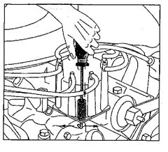
Figure 12-13:
Removing a distributor cap with screw clamps.
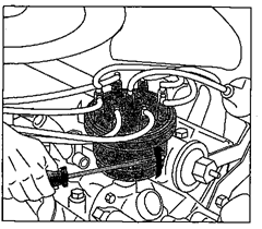
Figure 12-14:
Removing a distributor cap with clips.
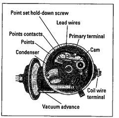
Figure 12-15:
The anatomy of a non-electronic distributor.
If, when you look inside your distributor cap, you do not find the parts in the illustrations in the following sections, you probably have an electronic ignition system and can consider yourself pretty lucky. As I mentioned earlier, you don’t have to deal with adjusting or replacing traditional points and condensers. All you have to do is check and change your spark plugs now and then and check for a defective distributor cap or rotor if your engine starts running roughly or stops running completely.
Because there are many types of electronic ignition systems, and adjustments usually require expensive tools and specialized expertise compared to conventional ignitions, I strongly advise you to rely on a good automotive technician if neither the cap nor the rotor appears damaged.
Remote the rotor
Sitting on top of everything else inside the distributor is the rotor. Rotors vary in size from small plastic gizmos that simply lift off the distributor shaft, to big round plastic plates that have two screws to remove (Figure 12-16 shows different kinds of rotors).
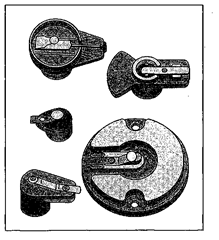
Figure 12-16:
Various types of rotors.
To remove your rotor, follow these steps:
1. Before you remove your rotor, move it on its shaft.
Does it move easily? If not, you really need this tune-up badly!
2. Remove the rotor from the shaft.
To remove a small rotor, just lift it straight up off the distributor shaft (see Figure 12-17). To remove a large rotor, you need to unscrew the two screws and lift the rotor off the distributor shaft (see Figure 12-18).
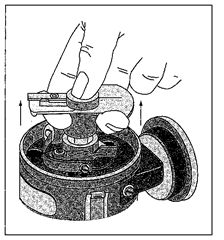
Figure 12-17:
Removing a small rotor.
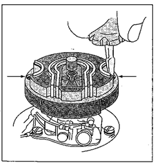
Figure 12-18:
You release this type of rotor by removing the screws.
3. Take a close look at the old rotor to see how it fits onto the shaft so that you can put the new one in properly later on.
All rotors go on in only one way: They either have a square-pin-in-square-hole/round-pin-in-round-hole arrangement, or they’re notched or shaped so that they fit on the shaft pointing in only one direction. Still, it’s a good habit to take a long look at anything you remove before you remove it, because you tend to forget how it’s situated, and sometimes you have to make a choice. Don’t be afraid to draw pictures if you aren’t sure you’ll remember how something fit together.
4. Look at the metal contacts that conduct current to the spark plug terminals.
If the rotor contacts are corroded, broken, or cracked, you really need a new one! In any case, plan to use the new one after you’re through working on the rest of the distributor.
5. Set the old rotor aside.
Under the rotor on some vehicles, you may find something called the centrifugal advance (see Figure 12-19). Its function is rather complicated, it has nothing to do with this minor tune-up, and it hardly ever breaks. Just leave it where it is and forget it.
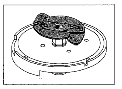
Figure 12-19:
A centrifugal advance.
Remove the static shield
On some vehicles, you may find a static shield, shown in Figure 12-20, which you have to remove before you can change your points and condenser. The static shield’s purpose is to prevent radio interference. Sometimes the working of the electrical system in your car produces strange noises on the car radio. This gizmo prevents that.
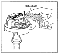
Figure 12-20:
The static shield.
The static shield isn’t hard to remove, but when you finish working on your distributor, be careful to put the shield back exactly the way it was. If you can’t get it back properly, don’t worry — your car will run perfectly without it, so just put the pieces in a paper bag and drive to your friendly service station. They’ll put it back for you (although you may have to take a little kidding).
Remove and replace the condenser
Under the rotor (and possibly the static shield) are the points and condenser. Before you remove the condenser, look at the two little wires, one leading to the points and the other to the condenser, that join together — usually with some sort of little screw and washer arrangement (refer to Figure 12-13).
Take a good look at how the wires (sometimes called leads) fit together in the gadget that holds them (called the primary terminal). The main purpose of the primary terminal is to prevent the clips at the ends of these wires from touching the floor of the distributor, which is called the breaker plate. If they touch the breaker plate, they short out and the car doesn’t start.
Now follow these steps:
1. Take a closer look at how the wires connect.
Are the little clips at the ends of the wires touching each other? Or are they separated with something? Does the screw that holds them in place touch them? Or is there something in between? Figures 12-21, 12-22, 12-23, and 12-24 show how to disconnect several types of primary terminal arrangements.
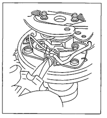
Figure 12-21:
On some distributors, the wires must be loosened from the primary terminal, as shown, before you can remove them.
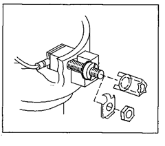
Figure 12-22:
On another type of distributor, you must use a special tool to remove the primary terminal nut and release the contact spring and lead wires.
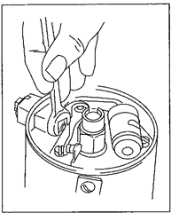
Figure 12-23:
On other distributors, the nut on the primary terminal must be loosened to release the contact spring and lead wires.
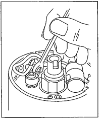
Figure 12-24:
Still another distributor has its wires attached as shown. You remove these by loosening the nut at the primary terminal.

Even if you think that you can remember exactly how the wires are connected, draw a picture of them before you remove them!
2. When you have a picture of how they are attached, disconnect the wires.
Put the screws or other parts that came off on a clean surface so that you’ll know where they are when you need them later.
3. Push the condenser (that little cylinder in there) through the ring that holds it, and then put it near the screws that you removed in Step 2.
Some condensers are attached to the clips that hold them, and you have to remove them, clip and all. Figures 12-25,12-26, and 12-27 show a few of the most common setups.
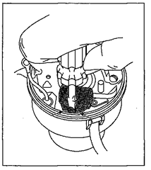
Figure 12-25:
This type of condenser has one screw to remove and two locating bumps to help you position the new one securely.
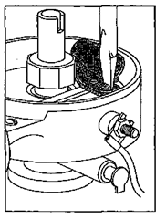
Figure 12-26:
Other condensers have a locating hole in the mounting bracket.
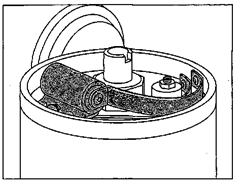
Figure 12-27:
Some condensers are connected to the primary terminal by a copper strap that must be released before they can be removed.
4. Use a clean, lint-free rag to wipe around the breaker plate where the condenser was resting. Then take the new condenser and slide it in where the old one was.
If there’s a new clip in the tune-up kit but you were able to slide your old condenser out without removing the old clip, forget the new clip as long as the old one seems to be in good condition and doesn’t wiggle around.
Congratulations! You just replaced your condenser. On to the points!
Remove and replace the points
The points on your vehicle may look a bit different from the ones in Figure 12-28, but they work the same way. Here’s a rundown of some basic types of points that you may encounter:
Some points are made in a single unit; others consist of two halves that fit together. Some Chrysler products have dual sets of points, but these are no more difficult to install or change.
Some foreign cars have little springs that come out separately from the points. If you have points like these, be sure to hold your free hand over the distributor when you loosen the points, or it will spring out and get lost.
Some points have two screws that fit into slots in the points — these can be loosened, and the points will slide out. Others have a screw to hold the points down and another screw to adjust them.
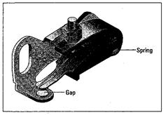
Figure 12-28:
A set of points.

Before you remove your old set of points, compare them to the new set of points you just bought. If they don’t look exactly alike, return them for the proper kind.
Once you know which kind of points you have, do the following:
1. Take your screwdriver and open up the points in your distributor so that you can see between them.
Are the contacts rough where they meet? This is usually the result of normal wear and tear. If they’re badly burned or pitted, the points should be replaced.
If the points are relatively new, excessive wear can be a sign that something is improperly adjusted or malfunctioning. Excessively worn points or burned points usually result from either poor adjustment when they were installed (this means that they were incorrectly gapped) or a bad condenser, or the accidental introduction of oil or cam lubricant between the point contacts.
Because used points are impossible to read accurately with a feeler gauge (Figure 12-29 shows you why), you won’t be able to tell if this is a case of poor adjustment. But if your olds points look badly burned or worn, be sure to check your new points after about 1,000 miles of driving, and if these look bad, too, ask your mechanic for an opinion.
2. Remove the old points by removing the screw or screws that hold them in place (see Figure 12-30).
If you have slotted points, simply loosen the screw and slide the points out.
This is a good time to use a screwholder. It holds the screw until you release it, so you don’t have to cram your fingers into the distributor to hold onto the screw.
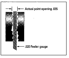
Figure 12-29:
Why you can’t get an accurate gap reading on old points.
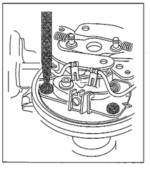
Figure 12-30:
Remove the screws that hold the points in place.
3. Put your old points aside, and use the clean rag that you used to clean around under the condenser to wipe the rest of the breaker plate (the floor of your distributor).
Before installing the new points, you need to do another little job.
Lubricate your distributor
Lubricating your distributor is something that seems inconsequential but is really very important because it can increase the life of your points. In the package with your new points, there may be a little capsule of cam lubricant. If there isn’t any, you can buy a tube of it very cheaply. Then follow these steps:
1. Take a little bit of cam lubricant on your index finger and wipe it around the sides of the cam wheel (see Figure 12-31).
Use the lubricant very sparingly. You don’t want lumps, just a nice greasy finish on the cam wheel only. If you don’t lubricate this wheel, your points could burn out very quickly. If you use too much, the stuff flies around inside the distributor when the wheel spins and fouls things up or causes your points to burn. Because your points open and close very fast (at around 12,000 times a minute when you drive a V-8 engine at 60 mph), you can see why the lubricant is necessary and why it tends to fly around if you’re too generous. You want just enough to make your cam wheel lobes slide easily past the points.
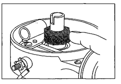
Figure 12-31:
Place only a small amount of lubricant on the cam wheel, or it will fly around and burn the points.
2. Look at the top of the distributor shaft, where the rotor was sitting. If there’s a wick inside it, place a few drops of light engine oil on the wick in the shaft, as shown in Figure 12-32.
If you don’t have the proper kind of oil, forget it this time and pick some up in time for the next tune-up.
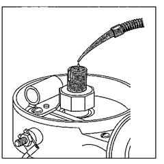
Figure 12-32:
If a wick is present, lubricate the distributor shaft with just a few drops of oil.
Install the new points
After the distributor is properly lubricated (see the preceding section), you’re ready to install your new points. Follow these simple steps:
1. Pick up the new points and gently rub the two contact tips together.
Points usually come from the factory with some kind of coating on them, and this coating can keep the spark from going across the gap. Gently rubbing the tips together removes this coating.
Don’t use cloth, paper, or a file to remove this coating — the lint or tiny filings will foul the points. A little rub is all they heed.
2. Install the new points where the old ones were (see Figures 12-33 and 12-34), but don’t tighten down the screws that hold them in place until you have adjusted the gap.
Sometimes it’s easier to connect the lead wires that come from the points and the condenser before you replace the points in the distributor.
3. Be sure that the clips on both wires touch each other but do not touch any other metal. They’re designed to go back to back so they fit snugly into the clip on the primary terminal.
Refer to Figures 12-21 through 12-24 to see the different types of configurations and the way to reassemble yours.

If you don’t see your configuration in these illustrations — and you neglected to make a drawing of the way yours was — use your imagination. If you get it wrong, your car simply won’t start until you get it right. Nothing else will happen, so don’t worry. Just fit the wire clips together and put them in the clip so that they’re not touching anything metal (this includes the side of the clip, if it’s made of metal, and the distributor base). As I said earlier, this can be done either before or after you get the points in place, whichever is easier.
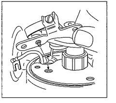
Figure 12-33:
Some points have a knob that fits into a locating hole on the floor of the distributor.
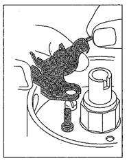
Figure 12-34:
Other points fit over a locating post on the floor of the distributor.
Adjust your points
Now it’s time to adjust your point gap (also called “gapping your points”). Before you can adjust the point gap, the little rubbing block that protrudes from the side of the points nearest the cam wheel must rest on the highest point of one of the cam lobes. This forces the points open to their widest gap — and that’s the gap you’re going to adjust:
1. If the rubbing block isn’t resting on the point of the cam lobe, use your ignition key to “bump” your starter until the cam wheel turns to the correct position (see Figures 12-35 and 12-36).
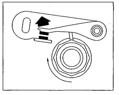
Figure 12-35:
The rubbing block causes the points to open when it is pushed up by the highest point on the cam lobe.
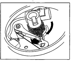
Figure 12-36:
Crank the engine with the starting motor until the point rubbing block is on the peak of the cam lobe. This brings the points to their widest gap.

If you have difficulty doing this, run a chalk mark down the side of the distributor and onto the base, or whatever it’s sitting on. (This line will help you later to get it back the way it was.) Then turn to the section called “Adjust your timing,” later in this chapter, to see how to locate the distributor hold-down clamp. Loosen it and turn the distributor until the rubbing block is resting on the point of the cam lobe and the points are wide open.
2. Look at your specifications for the proper point gap; then take your flat feeler gauge and select the correct blade.
3. Slide the blade of the feeler gauge between the points and note how narrow or wide the opening is.
Is the gap too small to let the blade in? If you left it like that, your car would be hard — or impossible — to start, and your points would get burnt and pitted. Is the gap so wide that the gauge doesn’t touch both surfaces as it goes in and out? This results in a weak spark and poor engine performance at high speeds. So if your gap is either too wide or too small, it needs adjusting.
There are three basic kinds of point-adjusting set-ups. Some cars have an adjusting screw (in addition to the screw or screws that hold the points in place). Other cars have an adjusting slot. Still others have a little window in the distributor cap that allows you to adjust the points without removing the distributor cap. Look at Figures 12-37, 12-38, and 12-39 to determine which one your vehicle has and then follow the appropriate set of steps:
If you have an adjusting screw, see Figure 12-37 and follow these steps:
1. Loosen the screw or screws that hold the points in place.
2. Turn the off-center adjusting screw.
3. Place the correct feeler gauge blade between the point contacts.
The contacts should still be at their widest gap. If they aren’t, follow Step 1 at the beginning of the “Adjust the points” section to turn the distributor until they are.
4. Turn the adjusting screw (see Figure 12-37) until the feeler gauge blade can slip in and out between the contacts, just touching them as it slides.
There should be a minuscule grab as the blade goes through, but it should go through easily. If you aren’t sure, try the next thicker and thinner blades. If the gap is correct, neither should work properly.

5. When you get the gap just right, tighten the screws that hold your points in place (nor the adjusting screw) and recheck with the gap with the gauge.
6. If you’ve moved the distributor, put it back where it was, with the chalk marks lined up.
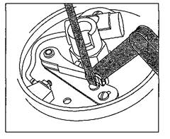
Figure 12-37:
Adjusting screw-type points.
If you have an adjusting slot, see Figure 12-38 and follow these steps:
1. Loosen the locking screw or screws that hold the points in place.
2. Make sure that the points are at their widest gap.
If they aren’t, follow Step 1 at the beginning of the “Adjust the points” section to move the distributor until they are. Then insert the tip of your screwdriver into the adjusting slot and, by moving it one way or the other, open the gap so that the correct feeler gauge blade can slip in.
3. Insert the correct feeler gauge blade and, using your screwdriver in the adjusting slot, adjust the contacts to allow the blade to slide in and out between the contacts, just touching them as it slides.
The blade should just touch both contacts as it moves, but it should move easily, with just a little bit of grab as it goes by. If you aren’t sure, try the next thicker and thinner feeler gauge blades. If the gap is correct, neither should work properly.
4. Tighten the screws that hold the points in place and then recheck the gap with the gauge.
5. If you moved the distributor, put it back the way it was, with the chalk marks lined up.
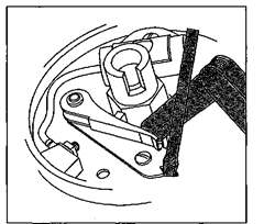
Figure 12-38:
Adjusting slot-type points.
If you have an external adjustment window, see Figure 12-39 and follow these steps:
1. Reassemble your distributor and put the distributor cap back on.
You can find instructions for doing so in the next section under “Replace the static shield” and “Replace the rotor.”
Your points probably won’t need adjusting because they come preset from the factory. They should need adjusting only if your car won’t start.
• If your car won’t start, first make sure that you’ve hooked the wires from the points and the condenser together so that they don’t touch any metal parts except each other. (See Step 3 of the section called “Install new points” for details.)
• If your points do need adjusting, follow the rest of these steps.
2. Use a hex wrench (an Allen wrench shaped to fit into hexagonal holes) to turn the adjusting nut behind the sliding window in the distributor cap, as shown Figure 12-39.
If a little hex wrench came with the points, use it. If not, you’ll have to get your own.
3. Start your car and leave the engine running with the emergency brake on and the car in either Park or Neutral. Turn the nut clockwise until the engine starts to falter. Then turn the screw half a turn counterclockwise, remove the wrench, and close the window.
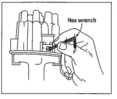
Figure 12-39:
Adjusting points with an external adjustment window.
Get it all together again
Once you’ve replaced the condenser, replaced and adjusted your points, and put those pesky little lead wires safely back in their clip, it’s just a matter of putting everything back the way it was before you started servicing the distributor. Relax; you’re in the home stretch. The next sections will see you safely to the winner’s circle.
Replace the static shield
If you have a static shield, put it back now, before you replace the rotor. For details, refer to “Remove the static shield” and Figure 12-20 in the earlier section called “Getting to the scene of the action.”
Replace the rotor
Now it’s time to install the new rotor you purchased.
Be sure to put the new rotor back exactly the way the old one went (the previous section called “Remove the rotor” may refresh your memory). All rotors fit properly one way only, and it’s easy to check the position of yours. Once it’s back on the shaft, just turn the rotor to see whether it settles back into place easily. If you can turn it in more than one direction, you haven’t replaced it properly.
Check the distributor cap
Take the time to clean and check your distributor cap thoroughly. If it’s defective, replace it:
Replacing a distributor cap is easy
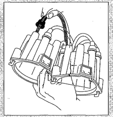
If your old cap is damaged, buy a new distributor cap for your vehicle’s make, model, and year at the parts department of your dealership or an auto supply store. Make sure that it looks exactly like the old one. The wires attached to the old cap snap in and out of it You should have no trouble moving the wires from one cap to the other if you hold the two caps side by side, in the same direction, noting the position of the locating lugs or slots (see the accompanying figure).
Then just pull the wires off the old cap one at a time and insert them in the new cap in the correct order.
Each wire must be placed on the tower on the new cap thafs in the same relative position as the tower on the old cap, or your car won’t run properly. Be sure to push each wire to the bottom of its tower and then push the rubber boot onto it securely.
1. Pick up the distributor cap (don’t let any wires come off) and take a look inside it. Wipe the inside clean with a lint-free rag.
Do you see any cracks in the cap when you hold it up and shine a light through it? If you do, you can buy another cap very cheaply. Follow the instructions in the sidebar called “Replacing a distributor cap is easy.”
2. Look at the inside of your cap where the wires enter it. Push gently on each wire where it enters its “tower,” and make sure that it’s in tightly.

Are the insides of the towers clean? Each little metal thing you see inside the cap is an electrode that transfers
electricity to the rotor; you don’t want these electrodes to be too fouled to conduct the electricity.
3. If the electrodes look dirty, scrape them with a small screwdriver to remove the carbon.
If the electrodes are burnt or very dirty, you may need to replace your wires. If you feel that you can do the job accurately, connecting each wire to the proper tower on the cap and the proper spark plug, one at a time, fine. If not, you’re probably better off having someone with more experience replace the wires for you.
4. When you’re satisfied that all is well, replace your distributor cap.
Figures 12-40 and 12-41 show you the two steps necessary to replace different types of caps.
5. Start your engine to see whether you’ve got everything right.
If your car starts right up, great! You’re ready to move on to the section called, “Checking and adjusting your work.” If the car won’t start, don’t panic; the instructions in the next section will soon set things right.
in the cap that fits over a boss on the distributor housing (right).
Figure 12-40:
Some distributor caps have either a locating lug that fits into a slot in the cap spring hanger (left), or a groove or slot in the cap that fits over a boss on the distributor housing (right).
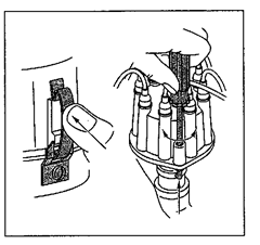
Figure 12-41:
Fasten the cap to the housing either by pressing on the center of the cap spring, forcing the spring over the mounting lugs on the cap (left), or by pressing down on the screw and turning it until the clamp is underthe slot on the bottom of the housing (right).
Restart your car
If your car doesn’t start (this isn’t unusual), the answer to one of these troubleshooting questions will solve your problem:
Is your vehicle still in Park or Neutral? It won’t start in any other gear.
Is your distributor cap on correctly? If it isn’t, put it on properly. If it is, remove it so that you can look inside and answer the other questions in this list.
Are the lead wires from the condenser and the points correctly replaced and tightened down? (Refer to Figure 12-13.) If they’re touching anything metal except each other, the spark is grounding out instead of passing through the points while they’re closed.
Are your points properly gapped? Check them again with the proper feeler gauge blade. Sometimes they move back together when you tighten them down after adjusting them.
Run a bit of very clean, lint-free cloth between them — maybe something got in there and is preventing the spark from going across. Do the points close completely? They must open and close to work.
Did you accidentally disconnect any other wires while you were working? Reattach them.
After you correct the problem, put your distributor cap back again and start the engine. It should start this time. Don’t panic if you still have trouble — almost everyone does the first time. But you ran the engine after you changed the spark plugs, so if there is a problem, it has to be in the distributor, right?
If you still can’t get the car started, remove the new condenser and put the old one back in. Maybe the new one is defective. This could also be true of the points or rotor. If you keep trying and still have no luck, the worst that can happen is that your friendly mechanic will have to get you out of the hole. So how bad can it be?
Check your distributor With a dwell meter
After you start your car following a tune-up, it’s time to check the dwell — assuming that you bought or borrowed a dwell meter. (You’ll also want to check your vehicle’s timing, following the instructions at the end of this chapter.)
The difference between the cost of doing this tune-up once yourself and paying to have it done for you is probably more than the cost of a dwell meter plus a timing light.
A dwell meter (see “What You Need to Do the Work in This Chapter” for a description of this and other tools) is a handy gadget for determining whether your points are properly gapped and whether your distributor is operating properly.
A dwell meter checks the distance that your distributor shaft rotates when your points are closed — which is the same as saying that it measures how long the points stay closed (or “dwell together”). This distance is called the cam angle, and, like all angles, it’s measured in degrees.
Hooking up a dwell meter
The first thing you have to do when you check the dwell is to hook up the dwell meter to the distributor. The following shows how to hook up two of the most popular types of dwell meters.


To hook up a dwell meter with two clips (see Figure 1242):
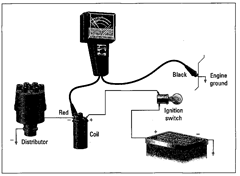
Figure 12-42:
How to hook up a two-clip dwell meter.
1. With the engine shut off, find the little wire on the side of the coil that connects at its other end to the distributor and hook the red clip to the clamp that holds that wire in place.
2. Hook the black clip to “ground.”
“Ground” can be anything on the vehicle that’s made of metal, through which electricity can pass back to the battery. In this case, ground can be any part of the metal frame of the car, but the best ground is an unpainted pipe or bolt bolted directly to the engine. (Not too near the carburetor, please! You don’t want a stray spark setting off the fuel in the carburetor.)
To hook up a dwell meter with three clips (see Figure 12-43):
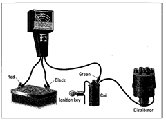
Figure 12-43:
How to hook up a three-clip dwell meter.
1. Connect the red clip to the positive terminal of the battery.
2. Connect the black clip to the negative terminal of the battery.
3. Connect the green clip to the clamp that holds the little wire on the side of the coil that connects at its other end to the distributor.
Some Ford cars have an insulated slip-on terminal on the wire leading from the distributor to the ignition coil. If you have a Ford with this configuration, lift the slip-on terminal and slide the Ford adapter clip in place (see Figure 12-44); then push the terminal down. Attach the Green clip to the adapter clip, as shown in Figure 12-44.
Don’t allow the Ford adapter clip to touch any other metallic part of the coil case or the engine.
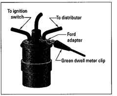
Figure 12-44:
How to hook up a dwell meter to some Ford cars.
Checking dwell
After your dwell meter is hooked up, follow these steps to check the dwell:
1. If your dwell meter has one, turn the calibrated knob to set it.
2. Turn the proper knob to the number of cylinders that your vehicle has.
3. Start the engine and let it idle, with the emergency brake on and the gearshift in Park or Neutral.
4. Look at the line on the dwell meter that has the same number of cylinders as your vehicle has, and see where the needle is pointing.
Is the needle pointing to the correct figure listed under “Dwell” on your specifications sheet? It can be plus or minus 2 degrees. For example, if your spec sheet shows a dwell of 38 degrees, a dwell anywhere between 36 and 40 degrees is fine. If the dwell is further off than that, you have to readjust your points, as explained in the next step.
5. Depending on whether you have a distributor with an external adjusting window (refer to Figure 12-39) or the kind of points that adjust with an adjusting screw or slot (Figures 12-37 and 12-38, respectively), do the following:
• If you have a distributor with an external adjusting window: Let the engine idle and keep the dwell meter in place. Then open the little window in the side of the distributor cap (it slides up) and turn the adjustment screw with the hex wrench until the needle on the dwell meter points to the correct number.
• If you have the kind of points that adjust with an adjusting screw or slot: Shut off the engine, remove the distributor cap again, and readjust your points to the correct gap with your flat feeler gauge by following the instructions in the section “Adjust your points.” When you’ve got it right, put everything back and check the dwell again. Sorry, but that’s life….

If the dwell is too low, the gap is too large, and vice versa.
When the dwell is correct, it’s time to check your timing, which is the topic of the next section. If you have a tach/dwell meter (a dwell meter with a tachometer built in), there’s one additional thing that you can do.
If you have a tach/dwell meter, turn the knob to set it to the tachometer readings. Some tach/dwell meters have both Hi and Lo readings; if yours does, you can choose either line. Start your engine and let the car idle. After it warms up a bit, check the tachometer to see at how many rpm (revolutions per minute) the car is idling. Try to keep the tach/dwell hooked up while you check your timing, but if it’s too difficult to clip both the tach/dwell and the timing light to the battery terminals, disconnect the tach/dwell and keep it handy.
Check your timing With a timing tight
Did you get a timing light? If you plan to check your timing, I hope you did. I’ve heard of a variety of ways to check your timing without one, but none of them has proven very accurate, and many turned out to be impossible. So beg or borrow one if you don’t want to buy one. The section “What You Need to Do the Work in This Chapter” tells you all about them.
As a last resort, if you have no timing light, you can drive down to your local service facility after you’ve done your tune-up and ask them to check your timing for you, but be prepared to deal with the consequences. Instead of using a timing light, the technicians will probably hook your car to an electronic diagnostic machine in order to give you an answer, so be sure to ask beforehand if there’s a charge for this service. If there is, ask whether the charge covers adjusting the timing for you, if it’s necessary. If they’re willing to check your timing for nothing and your timing is off, they’ll probably charge to adjust it for you. And if you tell them that you want to fix it yourself, you’d better plan to go somewhere else for a timing check when you’re through. Once you’ve exhausted all the garages in the neighborhood, you’ll probably have to go out and borrow or buy a timing light anyway!
To check your timing, follow these steps:
1. Read the instructions that came with the light.
Reading the instructions is a good idea with any piece of new equipment.
2. Hook up your timing light as suggested in those instructions.
Most lights have three clips on them. If you have no instructions, the ones in this topic will work for most timing lights with three clips (see Figure 12-45).
3. If you haven’t already turned your engine off, do so.
4. Clamp the big red clip to the positive terminal of your car battery, as shown in Figure 12-45.
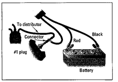
Figure 12-45:
Hooking up a three-clip timing light.
5. Clamp the big black clip on the negative terminal of the battery.
Make sure that the battery terminals are clean enough to allow current to pass through them. If they look very funky, scrape the clip around on them a little, or wash off the junk with a clean rag dipped in water and baking soda.
Try not to get the stuff from the battery terminals on your hands — it has acid in it. If you do get it on your hands, just wash them off with water; it won’t burn holes in you right away.
6. Attach the third clip (the one with the thickest insulation) to your #1 spark plug.
To find out where the #1 plug is on your vehicle, refer to Figures 12-2 through 12-8.

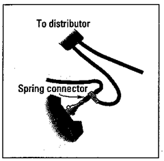
Figure 12-46:
Using a spring connector to attach the third clip to the #1 spark plug.
There are three ways to place the clip:
• You can remove the boot from the spark plug, put the clip on the terminal end of the plug that sticks out of the engine, and replace the boot so that it fits snugly and allows the current to pass through from the wire to the plug (refer to Figure 12-45).
• You can use a small metal spring or clip that fits over the terminal end of the plug, leaving a gap between the boot and the plug on which to clip the third clip from the timing light (refer to Figure 12-46).
• If your #1 spark plug is hard to get at, you can attach the third clip to the distributor terminal tower where the wire from the #1 plug enters the distributor cap. Just trace the wire from the plug to the distributor, remove the boot from the distributor cap terminal, add a metal extension (usually supplied with the light), replace the boot, and clamp the clip to the extension (see Figure 12-47).
7. With your engine still shut off, try to pull up on your fan belt with one hand to tighten it, and turn the fan with the other hand to rotate the wheel that has the fan belt hooked around it (the lower wheel).
This wheel, called the crankshaft pulley (or the harmonic balance wheel), probably has your timing marks on it (see Figures 12-48 and 12-49). On some vehicles, the timing marks are located elsewhere, so if you can’t find yours on the crankshaft pulley, consult your owner’s manual or service manual for their location, or call the service department at your dealership.
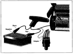
Figure 12-47:
Attaching the third clip to the #1 spark plug or the #1 distributor terminal.
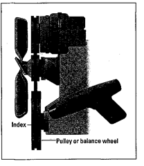
Figure 12-48:
Timing marks on the crankshaft pulley of a vehicle.
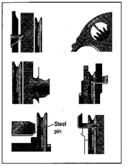
Figure 12-49:
Timing mark locations on other vehicles.
If you can’t move the fan by hand, remove the big wire from the center of your distributor cap and lay it on an unpainted metal part (not the carburetor!) to ground it. Then turn the key in the ignition to “bump” the starter without starting the engine. Doing so turns the crankshaft pulley, and as the pulley turns, a set of lines should come into view. These are your timing marks. A pointer attached to the engine block usually points to these marks. To set your timing, you have to get the pointer to point to the correct timing mark while the engine is running. Figures 12-48 and 12-49 show where the timing marks may be on your vehicle.
8. Look at your spec sheet to see what your timing degree should be.
The spec sheet (refer to Figure 12-1) will say something like “10°550,” which means that you want to line the pointer up with the 10° timing mark when the engine is idling at 550 rpm.
The spec sheet may say something about BTDC or ATDC. This simply means that your timing marks will have a line labeled 0, with marks above and below it. The 0 is top dead center (TDC). Depending on the direction that the wheel rotates, the lines that come into view before the 0 (or TDC mark) are “before top dead center” (BTDC), and the ones that appear after TDC are “after top dead center” (ATDC). In case you’re curious, “top dead center” is the point at which the piston reaches its highest point in the cylinder and compression is greatest. (How’s that for cocktail party chatter?)

9. Once you find the timing marks and know which mark to set your timing at, use a piece of chalk to make that mark stand out.
You can also chalk the tip of the pointer to make it more visible.
10. Attached to the side of your distributor is a round gizmo called a vacuum advance. Disconnect the little rubber hose that comes from it, and put a piece of tape on the end of the hose — or stick a screw in it — to seal it off (see Figure 12-50).
Some vehicles have distributors without vacuum advance mechanisms. If you have one of those vehicles, you may need to disconnect a special electrical connector. Consult a service manual or call your dealership if your vehicle has no vacuum advance.
11. Start your engine, making sure that your emergency brake is on and that you’re in Park or Neutral. Let the car warm up.
12. If your tach/dwell meter is still hooked up, look at the “rpm” line to see whether the car is idling at the proper speed. If you have no tach/dwell, check the idle speed on the dashboard tachometer.
If your car isn’t idling at the proper speed, you have to adjust your idle. Adjusting the idle is a simple matter of turning one screw, so don’t be dismayed. You can find instructions for doing this in the section called “Adjusting idle speed screws” in Chapter 13.
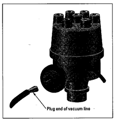
Figure 12-50:
Disconnecting the vacuum advance.
13. Aim the timing light at the timing marks and press the button on the light.
The fact that the light is hooked to your #1 cylinder spark plug means that current passes through the light every time your #1 plug “fires.” This makes the light go on and off with a strobe effect. As a result, the timing marks appear to be standing still, although the crankshaft pulley is actually turning rapidly. Fascinating, isn’t it?
14. Note to which timing mark the pointer is pointing.
Is it pointing to the correct mark? If it isn’t, you must adjust your timing — the focus of the next section.
Adjusting your timing
If you need to adjust your timing, follow these steps:
1. On the base of the distributor shaft, below the distributor, is a nut called the distributor hold-down clamp.
Use a combination wrench to loosen this nut so that the distributor can turn a bit on the shaft when you grasp the vacuum advance and move it back and forth.
If you have trouble reaching the hold-down clamp, a distributor wrench can make it easier (refer to Figure 2-5 in Chapter 2).
2. Move the distributor a little bit on the shaft; then shine your timing light at the timing marks again to see whether you got it right.
Is the pointer closer to the right mark? Is it farther away? If it’s farther away, you have moved the distributor in the wrong direction. Go back and move it the other way. Every time you move the distributor, go back and check again with the timing light.
3. Repeat Step 2 until the pointer is pointing to the correct timing mark.
If your idle speed changes, adjust your idle to specifications and recheck your timing. Then tighten the distributor hold-down clamp again, making sure that you don’t move the distributor when you do so. Check again with the light. Are the timing marks dead on? Good! (You can be off a little bit without causing trouble, but be as accurate as you can without driving yourself crazy.) You now have your car timed perfectly, which leads to much better engine performance and fuel consumption — and cuts down on air pollution.
4. Shut off your engine and disconnect the timing light and the tach/dwell meter.
If you’ve used a metal extension on your #1 plug, be sure to remove and put the boot back on the plug.
Well, you’ve changed your spark plugs, serviced your distributor, and checked your dwell, idle, and timing. You just completed a basic tune-up! If you had a little trouble, would it have been worth big bucks to avoid it? Probably not. (As I write this topic, the cost of tune-ups seems to be going up daily.) Plus, by doing the job yourself, you know that all the work has been done and done properly. Congratulations!
