Implementations and Results
TTL Relaxation
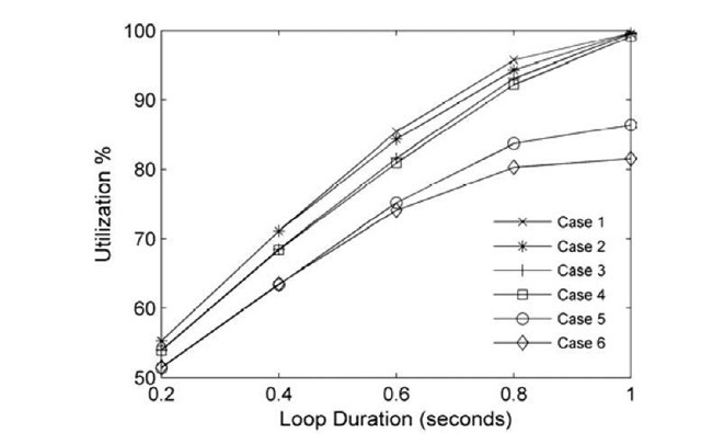
Fig 4 shows the utilization of the link containing the loop for all six cases, for varying loop durations, and without consideration of EPD. In the first four cases (1-4),utilization increases with the duration of the loop in a linear fashion until it reaches 100% when the loop duration is one second. In cases 1-4, the packets forming the total CWND of all TCP sources (WTotal) traverse the link four or more times, resulting in full link utilization. The benefit of TTL Relaxation is shown clearly in Case5 and Case6 where almost all packets were dropped (TTL expired) before full link utilization took place, because of the low RTTL of TCP packets in the loop. In both cases (Case 5 and Case 6) all the packets which are bottlenecked by the access router’s buffer don’t travel the link more than 3 times hence, full utilization does not occur.
Fig. 4. Utilization of the link containing the loop for all cases with different loop durations and different Rttl when entering the loop in each case
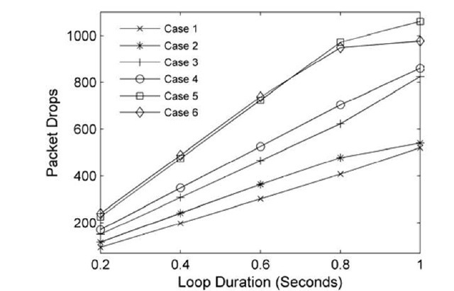
Fig. 5. Total TTL expirations during different loop durations
Fig 5 shows the total number of dropped packets (TTL expiration) in all six cases. The graph shows that when RTTL was small, more packets were dropped. Because the Rttl in Case 1 was the largest, almost half the packets were not dropped, which made the utilization reach 100%.
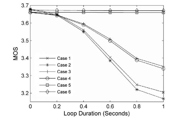
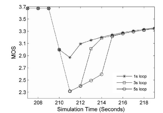
We expect that when the link is fully utilized during a loop, any traffic passing through it will be delayed as the node’s buffer becomes congested. To prove this point, the VoIP traffic which passes through the loop (but is not looping) was analyzed during the loop in order to see whether such real time traffic is affected and delayed by the loop. The Mean Opinion Score (MOS) which determines the quality of the call at the destination and which is presented by a numeric value ranging from 1 to 5 was analysed for the VoIP traffic. Fig 6 shows the average MOS value (as generated by the simulator) of the VoIP traffic as received by the VoIP receivers in all six cases during the loop. The graph shows that for Case5 and Case6 the MOS value stayed almost constant during the loop at approximately 3.7 (high quality) as the link was not fully utilized. The MOS value for the other four cases decreased as the duration of the loop increased until it reached about 3.1 during which the quality of the VoIP call degrades. Although in this case the VoIP traffic was not very greatly affected by the loop (because of the low RTTL), there are cases during which the quality of such traffic may become greatly compromised by the loop. In order to show a worst case scenario, the same simulation was repeated for Case1 except that RTTL was set to 64 and the loop duration was set to 1, 3 and 5 seconds respectively. Fig 7 shows the average MOS value of the VoIP traffic for this scenario. While the VoIP quality is still acceptable during the first second of the loop, it gets as low as 2 when the loop continues to exist. Such a low MOS value indicates that almost all the call receivers will be dissatisfied with the call quality, which degrades noticeably during the loop.
Fig. 6. The MOS value for the VoIP traffic that passes through the loop in all six cases for different loop durations
Fig. 7. VoIP MOS for Case1. RTTL is 64. The loop took place when the simulation time was 210 seconds.
TTL Relaxation with Big Loops
As the lifetime of the packet depends upon the number of nodes that it travels through, increasing the number of nodes participating in the loop should cause packets to be dropped sooner and hence reduce bandwidth consumption during the loop. Through changing the link metrics, a three-node loop was created between nodes TR, RO and BG and nodes HR, AT and SI with no traffic passing through the loop. In the first case where packets entered the loop with RTTL = 11, the utilization of links TR^RO and RO^BG was almost 100% while it decreased on link BG^TR to be 75%. This is because both nodes TR and RO sent the traffic four times while node BG sent the traffic only three times. In the second case where traffic enters the loop with Rttl = 8, the utilization of links HR^AT and AT^SI was almost 65% while it decreased on link SI^HR to 45%. The results show that TTL Relaxation reduces the bandwidth consumed in larger loops while limiting the number of links that are fully utilized by them.
TTL Relaxation and EPD
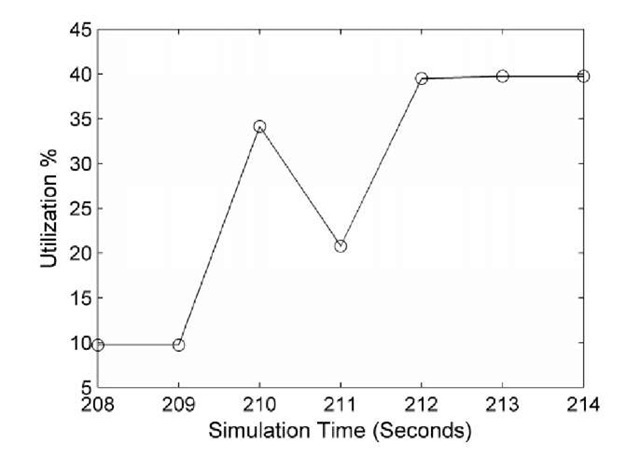
After implementing the algorithm in OPNET according to the analysis and equations provided earlier, the algorithm performed as expected and mitigated the loop in Cases 1, 2, 3 and 4 but not Cases 5 and 6 where the loop wasn’t expected to fully utilize the link according to the calculations. Fig 8 shows the utilization in the link containing the loop for Case1 when the loop duration was 1 second. The utilization was expected to be 100% during the loop (Fig 4) but the graph shows that the packets that bounced back from node BG were dropped by the Master node RO which marked the interface connected to node BG as an LMI interface. When the loop took place, node RO sent the traffic only once and this is why the utilization at that time was approximately 35%; 10% was VoIP traffic and 25% was TCP traffic which is determined by WTotal and is limited by the access router buffer. The algorithm was extended further to drop a certain number of packets during the loop (instead of dropping all the packets) in order to minimize the packet loss, although this is not discussed here due to space limitations.
Fig. 8. Link utilization in Case1 when the loop duration is 1 second with EPD applied. The loop took place when the simulation time was 210 seconds.
Efficient Early Packet Dropping
While the EPD algorithm mitigates the harmful loops by dropping all looped packets, it might be more efficient in some cases to drop a certain number of looped packets so that utilization during the loop doesn’t reach 100%, although some of the looped packets reach their destination. Such an increase in the efficiency of the algorithm will provide better quality for UDP Video-on-Demand and UDP video downloading. In these two cases dropping all the looped packets will increase the probability of the I-frames (compressed video frames that all the proceeding frames depend on) being dropped and hence, noticeable quality degradation will take place at the video receiver. Therefore, the equation in (7) can be altered so that:
Uioop is the utilization during the loop. Because the Master node knows the original utilization of the link that contains the loop, the Master node can calculate the number of packets that can loop in the link (SSafe) without causing the utilization to reach 100% while dropping the rest of the packets. In this case only LT is considered (maximum Loop Traversals) because once some packets have been dropped, the queuing delay will decrease causing the packets to circulate up to their maximum limit (TTLuAvrgeachable/2). For example, in Case1 when the loop duration is 1 second and a harmful loop is expected, the number of packets that may loop without causing the link to be fully utilized is:
Number of packets that need to be dropped
Number of packets that need to be dropped
The Drop Ratio can be rounded up to the next integer so that the Master node will drop 1 packet out of each 3 packets. After running the Efficient EPD algorithm, the utilization of the link containing the loop for Cases 1, 2, 3 and 4 was approximately 90% instead of 100% without EPD or 35% with EPD.
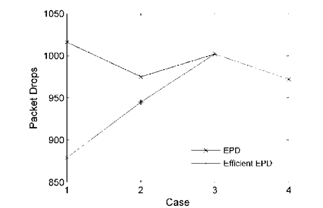
Fig 9 shows the total number of packet drops during the loop in all four cases with the implementation of either the EPD algorithm or Efficient EPD algorithm. The graph shows that when packets enter the loop with large Rttl, the efficient algorithm saves many packets from being dropped and allows them to be delivered to the destination. With small Rttl, there are normally the same number of packet drops, because the remaining packets that were not dropped by the efficient algorithm will circulate faster because of the decreased queuing delay, and will be dropped once their TTLs expire.
Fig. 9. Total number of packet drops for loop duration of 1 second when applying both algorithms
Conclusion
This paper introduced an easily implementable loop mitigation mechanism which mitigates routing loops that take place between two nodes in IGP networks only when the loop is predicted to utilize the link fully, which would congest router buffers and delay any traffic sharing links on the loop. The overall mechanism was divided into two sub-solutions; the first solution was based upon TTL Relaxation where the TTL of the packets entering the network is relaxed so that the packets caught in the loops are dropped sooner than before. The second part of the mechanism is the Early Packet Dropping mechanism which takes place only in cases where the loop is expected to utilize the link fully.
The TTL Relaxation scheme reduces bandwidth consumption in loops of any size, and minimizes the delay experienced by traffic passing through them, especially when the loop is close to the egress edge router. The VoIP traffic passing through loops closer to the source was slightly degraded (delay up to 130 ms) because of the small network diameter which implies that RTTL is small and hence packets are dropped sooner. In networks with large diameters, RTTL can be large which in turn causes the packets to circulate longer, potentially delaying VoIP traffic by more than 150 ms.
While the EPD mitigation mechanism mitigates the loop by dropping all the looped packets, the Efficient EPD mechanism showed better performance by dropping a certain number of packets, thus ensuring that the link won’t be fully utilized while delivering the rest of the packets to their final destination.
![tmp23131_thumb[2] tmp23131_thumb[2]](http://what-when-how.com/wp-content/uploads/2011/07/tmp23131_thumb2_thumb.jpg)
