Abstract
The run-time strategy for allocating the application tasks to platform resources in homogeneous Networks-on-Chip (NoCs) is enhanced with respect to minimising the communication energy consumption. As novel contribution, the entity Life-Time (LT) is incorporated to a node of an application characteristics graph (ACG), used for describing an incoming application. Several algorithms are then modified for solving the task allocation problem, while minimizing the communication energy consumption and network contention. If Life-Time(LT) is taken into consideration, it is observed that after each allocation, the nodes having lower value of life-time contains more available neighbors, compared to the existing solution, hence helps in allocation of an application as the system load increases, whereas the existing solution may fail to allocate the new application onto the current system configuration. Again, a node(used to describe a task in an application) belonging to an ACG is deallocated when its Life-Time expires which results in minimizing the communication energy consumption.
Keywords: NoC, Life-Time, SoC,Communication Energy Consumption.
Introduction
Today’s semiconductor fabrication technologies can integrate over billions of transistors on one chip. The complexity of the system increases dramatically because of the amounts of transistors on a single chip is proliferating. The concept of SoC emerges, as times require. SoCs can be fabricated by several technologies, including: Full custom, Standard cell and FPGA. With the increase in system complexity, the design of future Systems-on-chip(SoCs) faces major challenges. One among them is the design of the communication infrastructure.
In fact, the traditional bus-based or more complex hierarchical bus structures (e.g.,AMBA,STBus) cannot satisfy the performance, scalability, flexibility and energy efficiency requirements of future systems [1]. Network-on-Chip or Network-on-a-Chip (NoC or NOC) is a new approach to design the communication subsystem of System-on-a-Chip (SoC). NoC brings networking theories and systematic networking methods to on-chip communication and brings notable improvements over conventional bus systems.
Till now, the techniques proposed for the resource management for SoCs depend on a resource manager working under the control of an operating system [7]. Since SoC design is moving towards a communication-centric paradigm [8], the resource management process need to consider new parameter metrics (e.g., physical links with limited bandwidth, communication-energy minimization). In fact, with improper task assignment, the system performance will degrade. E.g., the "Random Allocation"scheme results in severe internal/external contention, which causes longer transmission latency and hence smaller system throughput.
The incoming applications, described by the Application Characteristic Graph are mapped onto multi-processing element SoC where communication happens via the Network-on-Chip (NoC) approach. Our work basically improves the proposed strategies [9] for minimizing the internal and external contention. Then these modified approaches are combined from a user perspective by a hybrid allocation scheme [9]. The new entity added in the allocation process is Life-Time (LT) of a node. Details on LT are given latter. The new entity LT improves the allocation (reduces the communication cost) of the application, for whose ACG, LT is associated to its vertices as well as the communication cost for additional mapping is also reduced. And reducing the communication cost is also considered as one of the important quality parameter of an allocation strategy.
In Section 2, we explain how this paper relates to other work. In Section 4 we describe the proposed work with the details of all the algorithms and finally we draw conclusions in Section 6.
Related Work
Task allocation is an important factor that influences performance optimization in parallel and distributed systems. To date, Contiguous and non-contiguous allocation techniques have been proposed for resource assignment to achieve i) Complete utilization of the system resources and ii) Maximize jobs performance [2,3,4,5,6]. In contiguous allocation, the processing elements are constrained to be physically adjacent. But the non-contiguous allocation scheme lifts the restriction of contiguity of processors [4].
The contiguous allocation can achieve only 34% to 66% resource utilization, while the non-contiguous allocation scheme can reach up to 78%. However, the performance of non-contiguous allocation may degrade due to internal and external contention [2], [4]. The internal contention is caused when two communication flows from the same application contend for the same link , whereas external contention is caused due to two communication flow from two different applications contend for the same link [5].
Pastrnak et. al in [10] has shown that by choosing the correct granularity of processing for enhanced parallelism and splitting time-critical tasks, a substantial improvement in processing efficiency can be obtained. Chang et. al in [11] solves the coarse-grain hardware/software partitioning and mapping of communicating processes in a generalized task graph by using an algorithm based on dynamic programming with binning. Murali et. al in [13] propose an off-line methodology for mapping multiple use-cases onto NoCs, where each use-case has different communication requirements and traffic patterns.
In terms of the on-line management, Nollet et. al in [7], for improving the system performance, task migration is applied by reconfiguring the hardware tiles. This paper features an OS that can manage communication on a packet-switched NoC. Moreira et. al propose an online resource allocation heuristic for multiprocessor SoC which can execute several real-time, streaming media jobs simultaneously. They can achieve resource utilization values up to 95% while handling a large number of job arrivals and departures [14]. Smit et. al in [12] propose a run-time task assignment algorithm on heterogeneous processors; with a constraint that either the task graphs consist of a small number of tasks or a task degree of no more than two.
The dynamic task allocation problem on NoC-based platforms is addressed in [1] and [16] considering the future addition of new applications. The user behavior information is used in the resource allocation process in [9] and [17]; which allows system to better respond to real-time changes and adapt dynamically to user needs. If user behavior is taken into account, about 60% communication energy is saved (with negligible energy and run-time overhead) compared to an arbitrary task allocation strategy. The detailed discussion of [9] and [17] work is given in Section 3.
Existing Solution
In the existing solution, dynamically task allocation is performed on NoC-based platforms by considering the user behavior [9]. The behavior of any user is defined as a set of consecutive, overlapping events spanning a given period of interaction between the user and the system. Let [ti, Q,t2] characterize an event where an application Q enters and then leaves the system during a specific time period between two arbitrary moments in time t\ and t2.
The three different approaches used by [9] are as follows:
— Approach 1: Primary goal is to minimize the internal contention and communication cost; minimize the external contention is always a secondary goal.
— Approach 2: Primary goal is to minimize the external contention; minimize the internal contention and communication cost is always a secondary goal.
— Hybrid approach: A hybrid method combines Approaches 1 and 2 while taking user behavior into consideration.
Here, a master processor keeps track of the user’s behavior for a long sequence of events. In the Hybrid approach, Approach 1 is applied only to the critical applications (having higher communication rate or present for a longer duration in the system); else applications are mapped onto the system using approach 2.
Here, the minimal-path routing is used to transmit data. For simplicity, the communication cost (i.e. energy consumption in bits, Eq of the event [ti, Q,t2] is defined as follows:
represents the Manhattan Distance between any two vertices,Where
connected to each other in Application Q.
Proposed Solution
Platform Description/Architecture
Our NoC is 2-D mesh architecture consisting of processing resources and network elements (Figure.1(a)). The master processor captures the user behavior and acts as a manager which is responsible for the process management. The slave processors are responsible for executing the tasks assigned by the master. The communication infrastructure consists of a Data Network and a Control Network, each containing routers (Ra and Rc) and channels connected to the processing resources via standard network interfaces (Dni or Cni in Figure.1(b)). In terms of functionality, the Data Network is meant for transmitting data under minimal-path routing scheme and wormhole switching. The Control Network is designed to deliver control messages from the slave processors back to the master processor notifying that the tasks assigned to them are done and they become available. Each slave processor can be considered as an independent sub-system; including a processin! g core (control unit and datapath) and its local memory (see Figure.1(b)). Here, it is assumed that the bandwidth of the links are sufficient enough to carry the load transmitted through them.
Application Model. Applications are encoded by the Application characteristics graph ACG. Each ACG = G(V, A) is represented as a directed graph and contains the following:
1. Nodes. Each node![]() contains a set of tasks obtained from an offline task partitioning process [10], [11]. The tasks belonging to the same node are allocated to the same idle PE. And each task will have worst case execution time WCET in order to meet the application deadline. In our proposed work, with each node
contains a set of tasks obtained from an offline task partitioning process [10], [11]. The tasks belonging to the same node are allocated to the same idle PE. And each task will have worst case execution time WCET in order to meet the application deadline. In our proposed work, with each node![]() one more parameter LT(vk) is associated. LT(vk) represents time interval between the arrival and departure of the node into the system. And how to calculate LT(vk) is defined later.
one more parameter LT(vk) is associated. LT(vk) represents time interval between the arrival and departure of the node into the system. And how to calculate LT(vk) is defined later.
Fig. 1. (a)The logical view of the control algorithm. (b)the on-chip router microarchitecture that handles the control network.(source – [9]).
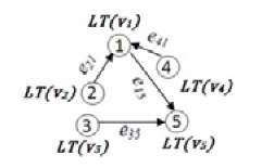
Fig. 2. ACG of an application
2. Edges. Each edge ei,j G E represents the inter-node communication from Vi to Vj , where node vi is any neighbor of node Vj . Weights w(ei,j) characterize the communication volume (bits per time unit) between nodes i and j.
When an event occurs (e.g., an application enters the system), our aim is to allocate the tasks belonging to this application to the available resources on the platform such that the internal/external network contention and communication cost can be minimized.
Communication Energy Model. The NoC platform follows wormhole switching and minimal-path routing. The communication cost (i.e. energy consumption in bits), Eq of the event [t1, Q,t2] is defined as follows:
The communication energy consumption is modeled using the bit energy metric in [15]. The total communication energy consumption of any application Q per time unit is calculated as follows:
where r(eij) is the communication rate of an arc in App Q(unit: bit per time unit), and Ebit(eij) stands for the energy consumption to send one bit from those processors where vertices i and j are allocated to (unit: Joule per bit). More precisely,
The term MD(eij) is the minimization objective; it represents the Manhattan Distance between the processors where vertices i and j are mapped to. The parameter Emu stands for the energy consumed in routers, including the crossbar switch and buffers, while Elink represents the energy consumed in one unit link, for one bit of data; these parameters are assumed to be constant.
The total communication energy consumed by all events in the system, during time interval t = 0 to T, is denoted by:
where N(t) is the total number of applications active in the system between time t — 1 and t. At each instant of time t, PAPP(i) is calculated, taking only the life edges of it.
User Behavior Model. The resource manager predicts the probability of a certain application being critical by recording and analyzing the events sequence for a specific user. When an event occurs, or an incoming application Q enters the system at time T, two ratios are used to determine whether or not this application is critical.
— Instantaneous communication rate ratio (a): the ratio between the communication rate of application Q (bits per time unit) and that of all applications occurring from time 0 to T. Application Q is set as critical if it has a higher communication rate than other applications.
— Cumulative communication energy ratio (ft): the ratio between the communication energy consumption of application Q active in the system (A(t) = 1 if Q is active between t — 1 and t and 0 otherwise) and energy of all events in the system from time 0 to T. For calculating Pappq, at each instant of time t only the live edges of Q are considered, as when the LT of an node expires, then it’s corresponding edges are also removed. If application Q has a higher event cost, then it is set as critical.
Run-Time Task Allocation Approaches
Two threshold values ath and ftth are set to solve the task allocation problem while including the user behavior. These values depend on the application communication rate and cost of events entering the system. If i) the rate ratio of an application, a, is higher than ath or ii) the energy ratio of an application, ft, is higher than, ftth then Approach 1 is used; otherwise Approach 2 is applied. Since building exact models for user behavior needs a long sequence of events, therefore, Approach 2 is applied in the beginning of the starting session. Next, four related sub-problems are formulated (namely, region forming, region rotation, region selection and application mapping) and efficient algorithms are presented for solving them.
Problem Formulation of Run-time Task Allocation Process. Before defining the problem statement, some related terms are defined below:
Region Forming Sub-problem (P1)
Given the ACG of an incoming application and the current system configuration. Find a region R and the corresponding location PL(vi) inside R, Vvi G V, in ACG which minimizes the communication cost:
If more than one region satisfies Equation 8, then select the region R with L(R) minimized.i.e. we select the region as convex as possible since this helps reducing external contention.
Region Rotation Sub-problem (P2)
Given an already formed region R (derived from P1) and the current configuration with region R’ containing the available resources Find a placement for the region R within R’ which: mm{L(R’ — R) }
Region Selection Sub-problem (P3)
Given the number of resources m required by the incoming application and the current configuration with region R’ containing the available resources Find a region R inside R’ with the number of locations in R equal to \V\ which: rmn {L(R) + L(R’ – R)}
Application Mapping Sub-problem (P4)
Given a selected region R (as derived from P3) and the ACG of the incoming application
Solving the Region Forming Sub-problem (P1)
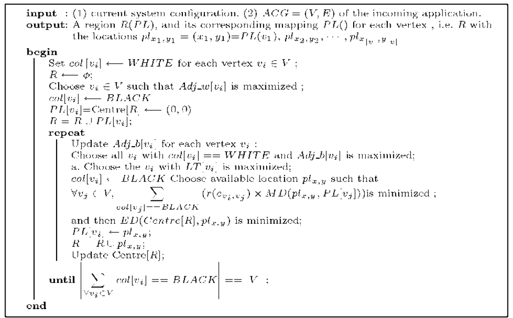
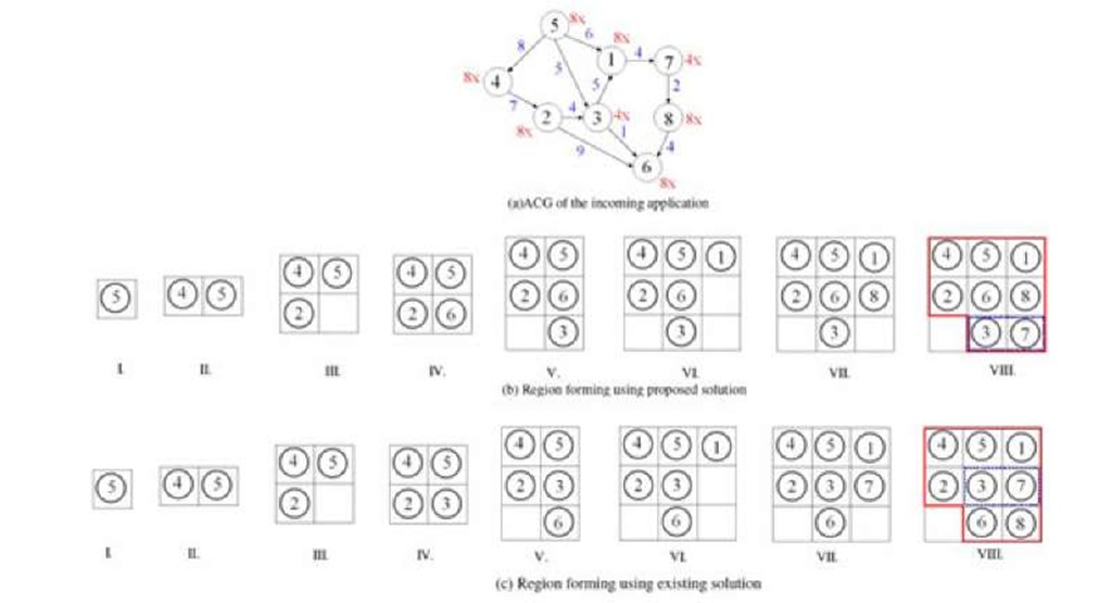
The region forming procedure is given in Algorithm1. If more than one node is selected for allocation in the proposed solution [9], then in the proposed solution, we will select the node having higher value of life-time for allocation. The same definitions [1], are used for various data-structures used in the algorithm1. The life-time of each vertex Vi G V is stored in the variable LT[vj]. An illustrative example is shown in Figure 3.
Algorithm 1. Region Forming Algorithm Solving the Region Rotation Sub-problem (P2)
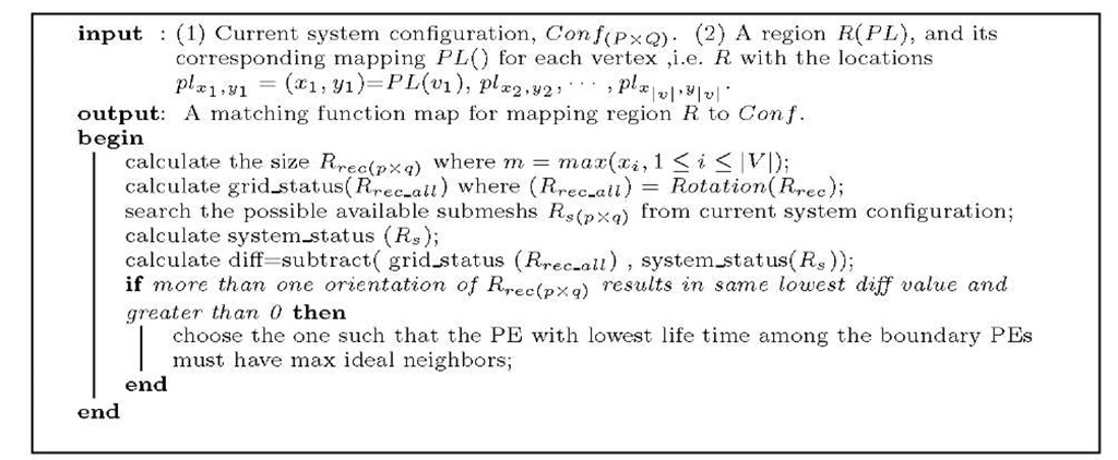
Solution to the sub-problem P2, finds a placement for the region found in the solution of the sub-problem P1 on the current configuration with the objective of fitting the region within the configuration as best as possible. The steps of region rotation algorithm are shown in Algorithm2. Here, too we have used the same definitions for various terms and metrics as given in [9]. One simple example is illustrated in Fig. 4. The resultant solution using proposed technique is Fig.5(b). The benefit obtained using this technique is that vertices v14 and vi5 have the lowest LT, so they will leave the system earlier,and can be used by any new incoming application with lower contention, but if Fig.5(a) solution is used, it incurs higher communication cost for an incoming application, resulting in higher external contention.
Fig. 3. Example showing the region forming algorithm on an ACG
Algorithm 2. Region rotation Algorithm

![(a)The logical view of the control algorithm. (b)the on-chip router microarchitecture that handles the control network.(source - [9]). (a)The logical view of the control algorithm. (b)the on-chip router microarchitecture that handles the control network.(source - [9]).](http://what-when-how.com/wp-content/uploads/2011/07/tmp23160_thumb.jpg)


