This section gives an outline of the methods in the SkinnedMesh, Skeleton and SkeletonNode classes used for vertex skinning. A description of these classes can be found in Sect. 4.8. A class diagram showing the relationships between the classes is given in Fig. C.1.
Fig. C.1 Relationships between the classes used for vertex skinning
SkeletonNode Class
The structure of the SkeletonNode class is similar to that of the GroupNode class.
Description:
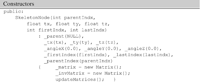
Every skeleton node is implicitly a group node, and can store references to a number of children in the list .children. A skeleton node represents a bone. It also stores a pair of indices _firstIndex and _lastIndex defining a range of mesh vertices that are attached to the bone. The translation parameters are stored in variables _tx, _ty, _tz, and the Euler angles in _angleX, _angleY, _angleZ. The overall transformation matrix and its inverse are updated whenever any of the joint angles is changed. Each node is assigned a unique index starting form 1. The index 0 is reserved for the root node which represents the origin of the world coordinate system. The parent index _parentIndex establishes the link between the current node and its parent node.
Description:
The non-default constructor uses the parameters read in from the input file to initialise each node. Note that each node contains two instances of the matrix class. Both the transformation matrix and its inverse are updated using the input parameters. There is also a default constructor that initializes all transformation parameters to 0.
Description:
These methods are exactly the same as the corresponding methods in the GroupNode class.
Description:
The translation parameters of the bones are set at the time of construction, and do not change afterwards. Only the translation of the base node (with respect to the world coordinate frame) is defined in the animation phase. This method is therefore usually invoked by the translateBase method of the Skeleton class.
Description:
These methods are used to set the rotation angle(s) of a bone during the animation phase. The methods are normally invoked by the rotate method of the Skeleton class.
Description:
These methods alter the vertex indices and the parent index of the current bone.
Description:
These methods allow you to examine the transformation matrices, vertex indices, the parent index and the number of children of the current node.
Description:
This method updates the transformation matrix and its inverse, and is invoked whenever any of the transformation parameters is changed.
Description:
The pre-processing phase builds the product matrix given in Eq. 4.9 and transforms the mesh vertex list to create a new list of vertices V’. The method preprocessPhase returns this new vertex list. The method in turn invokes transform1 which traverses the skeleton tree from the root, visits every node, combines the inverse translation components, and applies the transformation on the node’s vertex list.
Description:
In the animation phase, the updated matrices incorporating joint angle rotations are gathered in the form of a product matrix given in Eq. 4.10. The vertex list obtained from the pre-processing phase is transformed using the matrix. The transformed vertex coordinates returned by animationPhase are used for rendering the mesh for that particular frame. This method invokes transform2 which traverses the skeleton tree from the root, post-multiplies the product matrix with the matrix at the current node, and transforms the node’s vertices obtained from the pre-processing phase.
Skeleton Class
Description:
Each skeleton tree is referenced by its root node, stored in the variable _root. This node is created by the constructor. The base node (_base) is a special node in the skeleton tree that has the root node as its parent. The transformations of the base node define the position and the orientation of the entire mesh in the world coordinate frame. The class also maintains a list of references to the skeleton nodes as they are created by the loadSkeleton method.
Description:
The constructor creates the root node of the skeleton and initializes it with the default transformation parameters.
Description:
The getter method returns the reference to the root node.
Description:
This method loads skeleton data from a file formatted as shown in Fig. 4.18, and creates an instance of the SkeletonNode class for each bone. The method also calls attachBones that creates the hierarchical relationships between nodes (bones).
Description:
The translation parameters specifying the spatial offsets of each bone relative to its parent are assigned to the nodes through the constructor. These parameters are used for transforming vertices in the pre-processing phase. In the animation phase, only the joint angle rotations and the translation of the base node can change. The rotate method specifies the joint angles of the ith bone. The translateBase method changes the translation parameters of the base node. These two methods are usually called within the display loop of the application.
SkinnedMesh Class
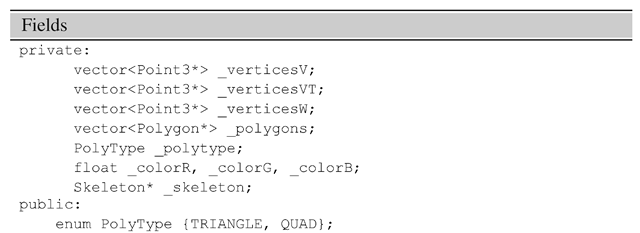
Description: The vertex lists verticesV, _verticesVT, _verticesW represent the lists V, V’, W shown in Fig. 4.11. The lists contain the mesh coordinates in the bind pose, after the pre-processing phase, and after the animation phase respectively. The polygon list .polygons store the vertex indices of the mesh polygons. For the sake of simplicity, each mesh is assigned a single material colour given by _colorR, _colorG, _colorB. A mesh can be either a triangular or a quad mesh. The variable .skeleton stores the reference to the skeleton associated with the mesh.
Description:
The constructor specifies only the polygon type of the mesh using the enumerated types TRIANGLE, and QUAD. Mesh data is loaded using loadMesh method. The application must also load skeleton data using an instance of the Skeleton class, and attach the skeleton object using the attachSkeleton method.
Description:
This method loads mesh data from a file formatted as shown in Fig. 4.19. The number of vertices per polygon in the file should match the polygon type provided to the constructor. The method also populates the vertex lists _verticesV and _verticesW with the initial vertex coordinates obtained from the file. The polygon list .polygons is also populated with polygon data.
Description:
The getter method returns the reference to the skeleton object attached to the current SkinnedMesh object.
Description:
The method sets a material colour for the entire mesh.
Description:
This method associates a skeleton object with the current mesh. The pre-processing of mesh vertices V to obtain an intermediate set of vertices V’ (Eq. 4.9) is also initiated at this stage.
Description:
This method is usually called inside the display loop of the application for redrawing the mesh with the updated joint angle configuration. Typically, this method is called after specifying the bone transformations using the rotate method of the Skeleton class.


