Vertex Skinning
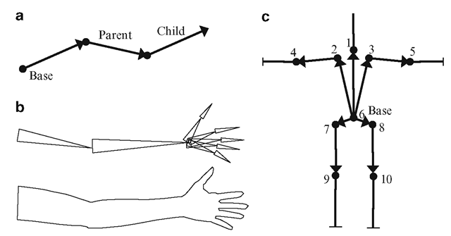
In order to define the hierarchical nature of a skeleton, the parent-child relationship between every two connected bones must be shown. We could represent a bone using a point with arrow(s) pointing to its child node(s), as in Figs. 4.7a, c. Another common representation of a bone uses triangles. Fig. 4.7b shows the mesh model of a human arm, and the associated skeleton consisting of a set of bones. Each bone stores the index of its parent and the bone’s position relative to its parent. Using this information, a complete hierarchical structure can be built, as shown in Fig. 4.7c. There are two special nodes in this skeleton tree. The root node always represents the origin of the world coordinate system, and has an index 0. The base node is that bone in the skeleton which has root as its parent. The position and the orientation of the base define the pose of the skeleton in the world coordinate space.
Bones are not physical structures present in a polygonal mesh, but are only animation tools or controlling mechanisms used to transform the mesh in a realistic manner. A bone also loosely represents the region of influence of a transformation.
The Bind Pose
The hierarchical organization of bones in a skeleton allows the geometric transformation for each bone to be defined with respect to its parent. The transformations that are associated with a bone are normally a joint angle rotation followed by a translation from its parent bone.
Fig. 4.7 (a) A simple joint chain. (b) A skeletal structure for the arm, hand and fingers. (c) Modified version of the skeleton in Fig. 4.5b
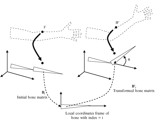
Fig. 4.8 Transformation of a mesh vertex V using the transformations of its bone
The translations of the bones, each relative to its parent, together define the initial configuration of a skeleton. For this configuration, the joint angles are set to 0. The corresponding mesh is said to be in the bind pose (Fig. 4.5a). The placement of bones in the skeleton can be obtained by first computing the axis-aligned bounding boxes (see Box 3.1 of Chap. 3) of vertex groups (defined as in Fig. 4.6), and then determining the joint positions for each box. Fig. 4.5b shows an example. For now, we will assume that each vertex is attached to one and only one bone. We will consider a more general case of associating a vertex with two or more bones, in Sect. 4.6. In the following section, we will see how joint angle transformations applied to bones can be transferred to mesh vertices attached to them.
Mesh Vertex Transformation
Consider a mesh vertex V attached to a bone i in bind pose (Fig. 4.8). In this configuration, each bone has an associated matrix Bi that defines the transformation from the bone’s local coordinate space to the skeleton’s coordinate space.
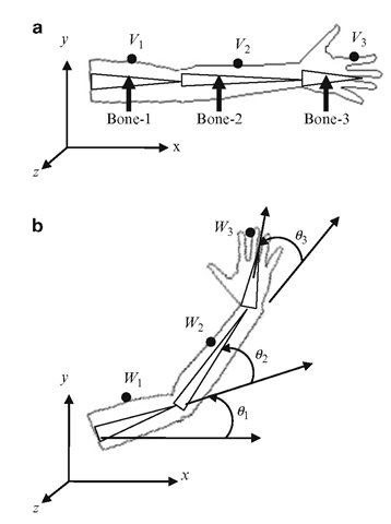
Fig. 4.9 An example showing transformations using three bones. (a) Bind pose and (b) transformed pose
This transformation depends only on the translations of bones in the hierarchy relative to their parents. The process of obtaining this transformation matrix will be discussed below. For a given joint rotation by an angle 6, the transformed configuration of the bone in the skeleton’s coordinate space is represented by another bone matrix B0; . To get the transformed vertex W, we transfer the original point V from the coordinate space of the mesh (which is the same as the skeleton space) back to its bone’s local coordinate space, and then apply the joint angle transformation to return to the skeleton space. In other words, the vertex V is first transformed using the inverse of the matrix B;, then by B0;. The first transformation gives the point B;_1 V. Applying the matrix B0; to this point yields coordinates of the transformed point W. Thus
The above equation is fundamental to skeletal animation, as it describes how transformations applied to a bone ; can be propagated to an attached mesh vertex V. The matrix B; depends only on the initial configuration of the skeleton, and therefore the points B; _1 V can be pre-computed and used for the entire animation sequence. As an example, we consider the model in Fig. 4.9, and show how it can be transformed using a skeleton comprising of three bones.
Let d1 denote the translation vector used for moving Bone-1 from its local coordinate space to the skeleton space. Let d2 denote the vector by which Bone-2 is translated in Bone-1’s coordinate space. The vector d3 similarly represents the translation of Bone-3 in the coordinate space of Bone-2. Vertices V1, V2, V3 are attached to Bone-1, Bone-2, and Bone-3 respectively on the mesh in its bind pose (Fig. 4.9a). We seek to find the transformed coordinates of these vertices, when the skeleton is transformed using joint angles 61, 62, 63 respectively as shown in Fig. 4.9b. If we represent translation matrices by T, the initial bone matrices are given by
When the bones are transformed using the joint angles, the bone matrices for the transformed configuration become
where R denotes a rotational transformation matrix. Now applying Eq. 4.5, we can write the expressions for the transformed vertex coordinates as
So far we have assumed that each vertex is associated with only a single bone. Section 4.6 discusses a more general case.
Vertex Skinning Using Scene Graphs
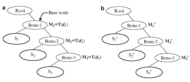
The vertex transformations (Eqs. 4.6, 4.7, 4.8) given in the previous section can be implemented using a scene graph for the skeleton. The scene graph is slightly different to the one we saw earlier in Chap. 3 (Fig. 3.3), in that each group node represents a bone with a matrix of the form M = TR defining the relative transformation of the bone with respect to its parent. Each bone has a child node representing the set of mesh vertices associated with that bone. In Fig. 4.10, Bone-1, Bone-2, and Bone-3 form a joint chain in a skeleton, and S2 denotes a set of mesh vertices associated with Bone-2.
Fig. 4.10 (a) Scene graph of a joint chain used for the pre-processing phase. (b) The updated mesh vertices in the animation phase
The initial bone matrix for Bone-3 is B3 = M1M2M3. The vectors Bi_1V in Eq. 4.5 are obtained in a pre-processing phase, where each vertex set is transformed using the inverses of the matrices attached to nodes. As shown in Eq. 4.6, these matrices involve only translation components, and their inverses (as well as the product of inverses) can be easily computed. In the example given in Fig. 4.10a, a vertex V belonging to the set S3 would be transformed into
As the tree is traversed from the root, matrices are combined by pre-multiplying the current product by the inverse of the matrix at the node, until a leaf node is reached. The vertices in a leaf node are transformed using the product of matrix inverses gathered up to that point. Thus the set S3 becomes a new set S30 after the transformation in Eq. 4.9. The transformed set of vertices replaces the original set for the animation phase (Fig. 4.10b).
In the animation phase, matrices at scene graph nodes are updated using the joint angles of the bones. The updated matrices are represented by M0 in Fig. 4.10b. The scene graph is again traversed from the root; matrices are combined, this time using post-multiplication, and applied to the vertices at leaf nodes to get the transformed mesh vertices. The vertices in the set S30 would transform according to the following equation:
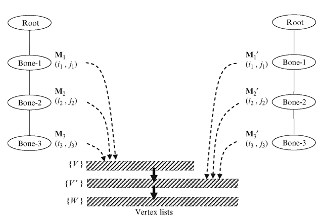
If the set of vertices attached to each bone can be specified as a range of indices (i, j) where i is the start index and j the end index of the set as in Fig. 4.6, then the structure of the scene graph can be simplified to a great extent as shown in Fig. 4.11. The vertex indices in the pre-processing phase point to the initial vertex list fV} of the mesh. After the pre-processing phase, they point to the list of intermediate vertices {V’} that are used as inputs in the animation phase. The transformed list of vertices {W} is used for rendering the mesh after applying joint angle rotations to the bones (Fig. 4.11).
Fig. 4.11 Simplified scene graph for a joint chain using a vertex index range for each bone
![tmpc2f9-149_thumb[2] tmpc2f9-149_thumb[2]](http://what-when-how.com/wp-content/uploads/2012/07/tmpc2f9149_thumb2_thumb.png)
![tmpc2f9-150_thumb[2] tmpc2f9-150_thumb[2]](http://what-when-how.com/wp-content/uploads/2012/07/tmpc2f9150_thumb2_thumb.png)
![tmpc2f9-151_thumb[2] tmpc2f9-151_thumb[2]](http://what-when-how.com/wp-content/uploads/2012/07/tmpc2f9151_thumb2_thumb.png)
![tmpc2f9-152_thumb[2] tmpc2f9-152_thumb[2]](http://what-when-how.com/wp-content/uploads/2012/07/tmpc2f9152_thumb2_thumb.png)
![tmpc2f9-154_thumb[2] tmpc2f9-154_thumb[2]](http://what-when-how.com/wp-content/uploads/2012/07/tmpc2f9154_thumb2_thumb.png)
![tmpc2f9-155_thumb[2] tmpc2f9-155_thumb[2]](http://what-when-how.com/wp-content/uploads/2012/07/tmpc2f9155_thumb2_thumb.png)
