Overview
This topic discusses concepts such as vertex blending, vertex skinning and keyframing that are fundamental to the animation of articulated character models. Vertex blending is the process of constructing blending surfaces between two different parts that move relative to each other, in order to create the appearance of a single deformable object. Vertex blending is useful in the animation of character models constructed by joining together several individual components.
Mesh models of animatable characters are often subdivided into groups of vertices that represent moveable body parts. A skeleton is an abstract representation of this form of partitioning of a mesh. Skeletal animation refers to the process of computing the transformations of each segment in the skeleton using joint angles, and mapping them on to mesh vertices. The topic discusses various stages in skeletal animation, describes the transformations applied to a mesh, and also outlines a scene graph based implementation.
Articulated Character Models
Animated character models can be found in numerous applications of computer graphics, ranging from simple computer games to virtual agents and computer generated feature films. Depending on the application requirements, the character mesh and the animation sequence can have varying levels of complexity. Sophisticated virtual character agents incorporate several forms of articulation including facial expression animation. In this topic we will look at the basics of human character animation with simple polygonal models and a small number of joint angles.
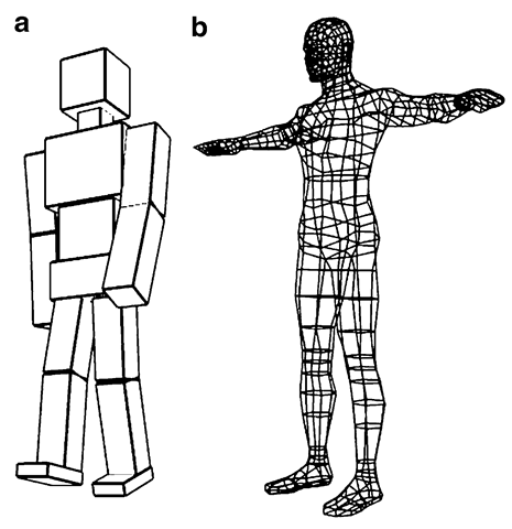
We broadly classify character models into two groups: (i) character models constructed using several objects or “parts” where each object is independently transformed and moved into its respective position within the model, and (ii) single mesh models that are animated by attaching vertices to different transformation groups. An example of each type is shown in Fig. 4.1. The first model, the “Glut Man”, is constructed entirely using scaled and transformed versions of cubes generated using glutSolidCube() or glutWireCube(), hence the name. The second belongs to the more commonly found class of mesh models.
Fig. 4.1 Character models constructed using (a) several component objects, and (b) a single mesh
In the case of the model constructed using individual parts, each component is first created in its own local coordinate space. A series of transformations is then applied to it based on where in a joint chain that component appears. This process, which is very similar to what we saw in the previous topic (Fig. 3.5), is repeated for every part of the model to reshape the character in a required pose. The transformations often have a well-defined hierarchical structure as discussed in the context of scene graphs. Figure 3.7 shows how the main body parts of a simple humanoid model are transformed.
A character model defined using a single mesh surface as in Fig. 4.1b requires a completely different set of coordinate transformations, as all mesh vertices are specified in a common reference system. However, we should be able to use the same set of joint angles to animate this model also, producing a similar effect such as a walk cycle. We can indeed construct a “virtual” skeleton consisting of joints and links that has a structure similar to our previous model in Fig. 4.1a. We can then associate the skeleton with the continuous mesh. This association is done by attaching a set of vertices belonging to each body part (e.g., forearm) to the corresponding link of the skeleton. The scene graph based transformations computed using joint angles can now be directly applied to the skeleton. The mesh vertices are transformed using a simple method introduced in Sect. 4.4.2.
If a model is made up of several parts as in Fig. 4.1a, where parts move or rotate relative to their neighbours, gaps can appear at joints when the model is animated. The next section addresses this problem, and introduces the method of vertex blending for creating deformable surface patches between parts that move relative to each other.
Vertex Blending
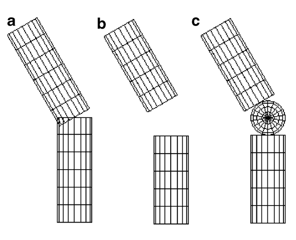
When two different mesh objects attached to a common pivot rotate by different angles, certain parts of the surfaces can interpenetrate, and gaps can appear on the opposite side (Fig. 4.2a). Repairing or "re-meshing” an area where two surfaces interpenetrate is a difficult task. Moveable surfaces are therefore often separated by a small distance from each other, so that they do not touch for the allowable range of movement or rotation angles (Fig. 4.2b). A sphere is sometimes placed at rotary joints, as in Fig. 4.2c, to fill the gap. While this approach is suitable for robot-like models, interpolation methods could be used for obtaining a better approximation of blending surfaces between moving parts. The process of creating such in-between surfaces is called vertex blending.
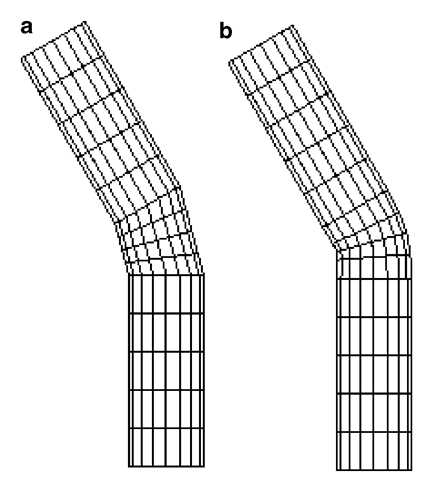
Corresponding pairs of points on two moving parts can be joined together to form a triangular or quadrilateral element belonging to the intermediate surface. These elements could be further subdivided using a simple linear interpolation formula (Eq. 2.43) to get a tessellated surface (Fig. 4.3a). We discuss below higher order interpolation methods for generating blending surfaces (Fig. 4.3b).
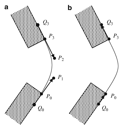
We can use cubic Bezier polynomials to generate interpolating curves between moving parts with tangential continuity at end points. In Fig. 4.4a, Po and P3 denote a pair of corresponding points on two moving parts of a character model. Q0 and Q3 are two points on the surfaces that are selected to define the local tangent directions P0—Q0 and P3—Q3 respectively. Using these tangent directions, we can specify two more points, Pi and P2, as
where a is a positive quantity used to increase or decrease the length of the tangent vectors P1 — P0 and P2 — P3. Points on the interpolating Bezier curve are generated using the parametric equation (see Box 2.4, Sect. 2.7)
Fig. 4.2 (a) Moving parts of an animated model can interpenetrate and form gaps at joints. (b) Links can be separated by a short distance to avoid surface intersections. (c) A sphere is sometimes attached to a rotary joint to fill the gap between two moving parts
Fig. 4.3 Generation of blending surfaces using
(a) linear interpolation and
(b) Hermite interpolation
Fig. 4.4 Generation of a blending surface using
(a) Bezier interpolation and
(b) Hermite interpolation
Substituting the expressions from Eq. 4.1 in the above equation gives
When a is increased, the weight of the tangent vectors on the interpolating curve is increased, and the curve gets closer to the tangents at the end points P0, P3. Care should be taken to ensure that the points P0, P1 both lie on the same side of the tangent P2 — P3, and similarly points P2, P3 lie on the same side of the tangent P1 — P0. Setting a large value of a violates this condition, resulting in a distorted Bezier curve.
A second interpolation method that is suitable for vertex blending is Hermite interpolation. Here, the tangent directions are defined using vectors P0—Q0 and Q3 — P3 (Fig. 4.4b), and the interpolating curve is given by
The coefficients of P0, P3 are exactly same as that of Bezier interpolation. Since tangents are defined along the direction of the curve from P0 to P3, Hermite interpolation does not have problems associated with large a values. Hermite and other types of approximating splines are discussed in more detail in Chap. 7.
Skeleton and Skin
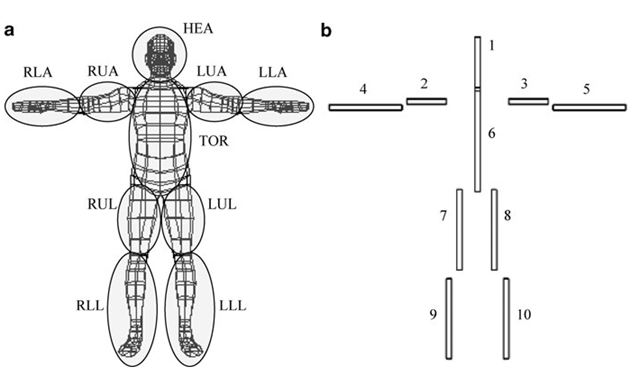
Animating a three-dimensional character model (Fig. 4.1b) containing hundreds of vertices and polygons can be a challenging task. This task can be simplified to a great extent by grouping together a number of mesh vertices as forming body parts that move as a single unit, connected together by a set of joints. A human model may be modelled as a collection of body parts with joints at neck, shoulders, elbows, wrists, hips, knees, and ankles. The grouping of mesh primitives into body parts and the definition of joints depend on the complexity of the animation. In a simple walk sequence, for instance, the arms and legs could be considered as the only parts that move relative to the main body. For a more complex animation, one might require movement of the head, hands, fingers, facial muscle regions, and so on. Figure 4.5a shows how points in a mesh could be grouped into ten body parts: head (HEA), torso (TOR), left upper arm (LUA), left lower arm (LLA), right upper arm (RUA), right lower arm (RLA), left upper leg (LUL), lower left leg (LLL), right upper leg (RUL), and right lower leg (RLL). Every group can then have an abstract representation called a bone. The complete set of bones, along with their connectivity information, is called a skeleton (Fig. 4.5b).
The notion of a skeleton consisting of a set of joint chains comprised of bones is central to articulated character animation. A skeleton can be easily animated; i.e., the transformations for the bones can be easily determined given the angles at each joint. The skeleton has the hierarchical structure similar to that of the model in Fig. 4.1a, the main difference being that in a skeleton, each component or bone is just an abstract structure, not a graphics primitive. A bone essentially stores information about its position and orientation relative to its parent in the skeleton.
Fig. 4.5 (a) Vertices in a mesh model are grouped together into parts that move relative to each other. (b) A skeleton definition formed based on a vertex grouping
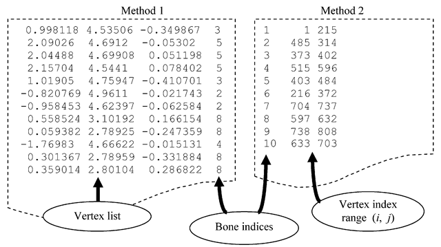
Fig. 4.6 Two simple ways of associating vertices with bones of a skeleton
Every bone is given a unique index as shown in Fig. 4.5b. Vertices belonging to a group are associated with a bone using the bone’s index. The part of a mesh represented by a bone is called its skin. In the example given in Fig. 4.5, the skin of bone “8” is the mesh segment that belongs to the set LUL. Two simple ways of associating groups of vertices with bones are shown in Fig. 4.6. In the first method, every entry in the vertex list is appended with a bone index. This method is suitable when vertices need to be associated with more than one bone (we will discuss this process later in Sect. 4.6). If several consecutive entries in the vertex list have the same bone index, then the second method is preferred where the minimum and maximum indices of a range of vertices are stored against a bone index.
