Sample Implementation
In this section, we will discuss the design of a set of classes that implement the functionality of a scene graph with transformation matrices attached to its nodes. Internal nodes that can store a list of children, and also a transformation matrix, are represented by the class GroupNode. All transformation matrices are assumed to have the general form given by T(v)R(6). The properties of leaf nodes are specified by three classes: ObjectNode that can represent a three-dimensional object, CameraNode that represents the camera, and LightNode that represents a light source. These three classes are derived from GroupNode so that we can store all child nodes (including group nodes and object nodes) with the same type, and also use polymorphic functions to implement tree traversal algorithms.
Group Node
The declarations of attributes and functions of GroupNode can be found in Listing 3.1 below. The primary functions associated with a group node include adding and removing children, and setting the transformation parameters. We use the List container of the Standard Template Library (STL) for storing references to the child nodes. The data members _angleX, _angleY, _angleZ specify the Euler angles of rotation about the principal axes of the group’s coordinate frame. Similarly _tx, _ty, _tz denote the components of the translation vector along the principal axes directions. Together, these attributes define the composite transformation for the group node in the form T(v) Rz( z) Ry( y)Rx( x), where v is the translation vector, and s denote Euler angles. The function render() is called on the root node to render the scene.
Listing 3.1 Class definition for a group node
Object Node
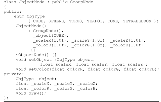
The class definition for an object node must cater to the requirements of defining and storing three-dimensional object models. Listing 3.2 gives the declarations of important attributes and functions of the class. To simplify the implementation, we use only the built-in objects provided by the GL Utility Toolkit (GLUT) of the OpenGL API. These objects are assigned numbers using the enumerated type ObjType. When an object is initially defined using the setObject() function, it may also be optionally scaled using parameters _scaleX, _scaleY and _scaleZ. These parameters are used to set the values of the corresponding data members of the class. An object may also be given a material colour using the function setColor(). A scene is rendered by calling the function render() of the GroupNode class on an instance that represents the scene graph’s root. This function in turn calls the polymorphic function draw() which is declared as virtual in GroupNode. The implementation of the function in ObjectNode will call the necessary OpenGL functions to apply the transformations and to draw the object.
Listing 3.2 Class definition for an object node
Camera Node
Any three-dimensional scene is assumed to have an active camera that contains information about the projective transformation used while rendering the scene. The camera also provides the view matrix needed for the transformation of vertices to the eye coordinate space. A camera can be added to a scene graph as a special type of object node. Listing 3.3 gives the class definition for the camera node. Since only one instance of the camera is used in a scene at any point in time, the class cameraNode is defined as a singleton class. It has a private constructor, and the static instance is made available to a program using the function getInstance(). The frustum parameters are specified by an application by calling the function perspective(). The function projection() uses these parameters to set up the projection matrix, and is called by render() of the GroupNode class. The view transformation matrix is constructed by the function viewTransform() by traversing the tree along the path from the camera node to the root node (Fig. 3.11). The class does not store any drawable object, and therefore draw() has an empty function body.
Light Node
The LightNode class as defined in Listing 3.4 has a simple structure containing no public functions other than the constructor. The constructor accepts a single integer between 0 and 7 as the argument which directly represents one of the OpenGL light sources GL_LIGHT0, … ,GL_LIGHT7.
Listing 3.3 Class definition for a camera node
Listing 3.4 Class definition for a light node
In OpenGL, light sources are transformed like any other point. The function draw() defines the initial position of the light source at (0,0,0), and transforms it exactly like its counterpart in ObjectNode. The class does not store or set any other light or material properties. They can be set by the application by directly calling the appropriate OpenGL functions. The same applies to setting OpenGL states such as enabling lighting, selecting two sided lighting, enabling colour material, and so on.
The sample implementation of a scene graph discussed above concatenates only transformation matrices along different paths from the root node to the leaf nodes. The hierarchical structure of a scene graph allows several other attributes to be propagated from an internal node to object nodes through various branches. One such attribute is the visibility of a node. If a node’s visibility attribute is set to false, then the visibility attribute of every node in that sub-tree can also be implicitly set to false by using a logical AND operation with the values from the parent nodes. Thus an object node will not be rendered if any of its ancestors has a visibility attribute set to false. A similar attribute that can be attached to the nodes is transparency. The transparency values can be multiplied together along every path from the root node, to determine the net transparency of objects stored in the leaf nodes.
First-Person View
The design of the camera node as outlined in the previous section permits a highly flexible implementation of a scene graph, since the only static instance of the class can be obtained anywhere by calling the getInstance() function. The camera node need not even be a part of the scene graph, if the camera is meant to be in a fixed location with respect to the scene. In this case, the transformations defined for the camera node specify the position and the orientation of the camera with respect to the origin of the world coordinate frame. These transformations will be directly used to obtain the view matrix for the whole scene.
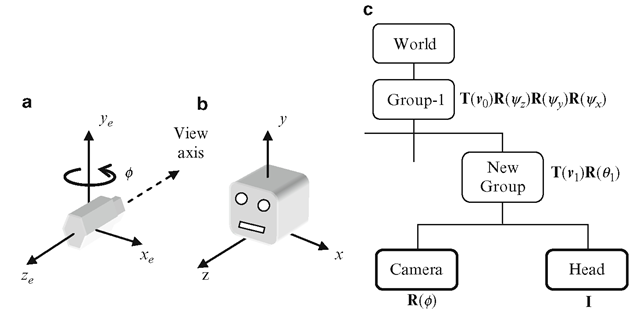
Often you will require the first-person view of a scene with the camera placed on a moving object. For the articulated character model in Fig. 3.7, the first-person view is provided when the camera is attached to the head. This is done by first applying transformations to the camera node so that it points to the right direction in the coordinate frame of the object node to which it should be attached. In the scene graph, the object node is replaced by a new group node. Both the camera node and the object node are attached to the new group node as its children. Figure 3.16 shows the reference frame (xe, ye, ze) of the camera and the coordinate frame (x, y, z) of the head of the character model. The camera initially points towards -ze direction. It is rotated about the y-axis by 180° to point towards the head direction. This transformation is represented by the matrix R(0). Figure 3.16 also shows the modified portion of the scene graph in Fig. 3.7 with the addition of a new group node and the camera node.
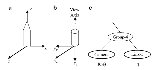
Now consider the 5-link joint chain shown in Fig. 3.3. Robotic arms such as this can be found in autonomous systems for inspection, welding and painting. The arm is driven by feeding joint angles to the controllers. Some constraints may be applied to the joint angles based on the application requirements. For example, a robotic arm for welding or painting may require the end effector (denoted by Link-5 in Fig. 3.3) to be kept in a horizontal position. It may also be required to have a camera attached to the end effector to obtain a clear perspective of the surrounding scene from its viewpoint. The graphical rendering of the scene as viewed from the position of Link-5 can be obtained by adding the camera node to the group node Group-4 as shown in Fig. 3.17.
From the previous examples, we have seen that the first step in the process of attaching a camera to an object node is to determine the transformation R(0 ) necessary to appropriately orient the camera in the local coordinate frame of the object. In the example in Fig. 3.17, this composite transformation comprises of two rotations: a rotation of 90° about the x-axis followed by another rotation of —90° about they-axis. The transformation functions given in Listing 3.1 allow us to define such rotations. It is also important to note that when a new group node is formed with the camera node and the object node as its children, transformations that were previously applied to the object node should now be applied to the camera as well. Therefore, the transformation matrix that was attached to the object node must now be transferred to the common group node. This would often leave the object node with the identity matrix as shown in Fig. 3.17.
Fig. 3.16 (a) Camera coordinate system. (b) A 3D object “Head” in its local coordinate frame. (c) The modified portion of the scene graph in Fig. 3.7, with the camera node attached
Fig. 3.17 (a) Local coordinate frame of a link of the joint chain in Fig. 3.3. (b) The desired orientation of the camera frame relative to the frame of the link. (c) Addition of the camera node to the scene graph in Fig. 3.3
Summary
Scene graphs are powerful data structures that can be used for hierarchical representations of transformations, bounding volumes and other visual attributes of groups of objects in a scene. This topic showed the application of scene graphs in defining the transformations of interconnected systems. Robotic manipulator arms and articulated character models are examples of such systems containing one or more joint chains. Using a scene graph, the relative transformation of one object with respect to another can be easily computed. Relative transformations are useful for displaying billboards and first person views. This topic also introduced the definition of a scene graph in the standard form. An object oriented framework for a scene graph was presented and some of the key implementation aspects were discussed.
The next topic will show that scene graphs play an important role in skeletal animation. Skeletal structures and the associated hierarchical transformations used in vertex skinning algorithms fit perfectly well with the scene graph model.


