Mesh Data Structures
Mesh data structures are designed to provide information about both mesh geometry and topology so that they could be used for fast traversal and processing of meshes. A large number of mesh operations extensively use information about mesh connectivity and local orientation around vertices. Mesh data structures also support efficient processing of incidence and adjacency queries. In this section, we consider one face-based and two edge-based data structures.
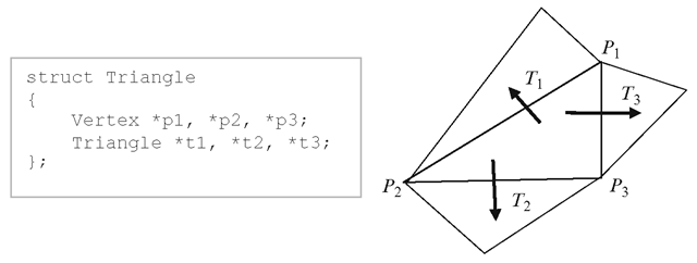
Fig. 8.8 A face based data structure for a triangle showing references to its neighbouring faces
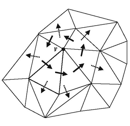
Fig. 8.9 Traversal of the one-ring neighbourhood of a vertex using a face-based data structure
Face-Based Data Structure
Face-based data structures are primarily used for triangular meshes where both the number of edges and number of vertices per face have a constant value 3. In an ordinary mesh file, each triangle is defined using the indices of its three vertices. A face-based data structure additionally stores references to its three neighbouring triangles (Fig. 8.8). Because of its simple structure, a face data structure can be easily constructed from a vertex list and a face list. This data structure does not store any edge related information, and hence is not particularly suitable for edge operations such as edge collapse, edge flipping or edge traversal.
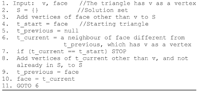
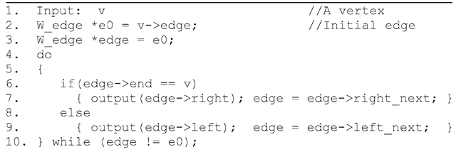
Assuming that every polygonal face in a mesh is a triangle, the face-based data structure provides a convenient mechanism to obtain information about all triangles surrounding a vertex. Using this information, we could perform the traversal of the one-ring neighbourhood of a vertex in constant time. The inputs for the algorithm are a vertex v and a triangle containing that vertex. The algorithm iteratively visits the neighbouring triangles, each time checking if the triangle has v as one of its vertices and has not been visited previously. In Fig. 8.9, the triangles indicated by dotted arrows are not visited as they do not have v as a vertex. The vertices of the visited triangles are added to the set of one-ring neighbours of v. A pseudo-code of this method is given in Listing 8.1.
Listing 8.1 Pseudo code for the one-ring neighbourhood traversal algorithm
Table 8.1 Components of the wing-edge structure for the same edge in opposite directions
|
Edge |
start |
end |
left |
right |
left_prev |
left_next |
right_prev |
right_next |
|
PQ |
P |
Q |
L |
R |
a |
b |
c |
d |
|
QP |
Q |
P |
R |
L |
c |
d |
a |
b |
Winged-Edge Data Structure
The winged-edge data structure is one of the powerful representations of an orientable mesh that could be used for a variety of edge-based query processing and manipulation of a mesh. In this representation, each face has a clockwise ordering of its vertices and edges. The structure stores several interconnected information pertaining to the neighbourhood of every edge in the form of three substructures: an edge table, a vertex table and a face table.
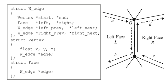
An edge PQ and its adjacent faces are shown in Fig. 8.10. The direction of the edge is specified by the start and end vertices, and it enables us to define the left and right sides of the edge. The corresponding references to the polygon L on its left, and R on its right are stored. The edge structure also stores the preceding and succeeding edges of PQ with respect to each of these faces. The preceding edge on the left is the edge a, and the succeeding edge on the left is the edge b. Similarly, the preceding edge on the right is c, and the succeeding edge on the right d. Note that on each face, a clockwise ordering of the edges is used. Table 8.1 shows how the component values change when the direction of the same edge is reversed.
The winged-edge structure also requires two additional tables or structures, as shown in Fig. 8.10. The vertex table stores the coordinates of each vertex and one of the edges incident to that vertex. The face table maps each face to one of the edges of that face. These tables provide the entry points to the edge structure via either a vertex or a face. For example, if we are required to find all edges that end at a given vertex v, we first use the vertex table to find one of the edges incident at v, and then use the winged-edge structure to iteratively find the remaining edges. Care must be taken to use the right orientation of an edge; the edge entry for a vertex v in the vertex table may have v as the either the start vertex or the end vertex. Similarly an edge in the face table may have the face as either its left face or the right face of the edge.
Fig. 8.10 The winged-edge data structure
Fig. 8.11 Computation of all edges incident at a vertex. Both directions of an edge should be considered in algorithms using the winged-edge data structure
Listing 8.2 Pseudo code for finding all edges through a vertex in anticlockwise order
The algorithm to find all edges incident at a vertex v considers both the cases discussed above, and enumerates the edges surrounding v in an anticlockwise order (Fig. 8.11). The pseudo-code for the algorithm is given in Listing 8.2.
Listing 8.3 Pseudo code for finding all faces that share a vertex in anticlockwise order
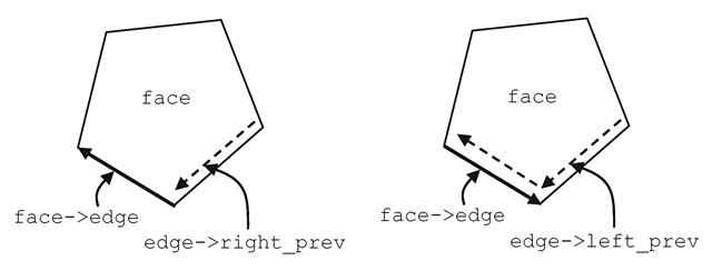
Fig. 8.12 Computation of edges around a polygonal face
Listing 8.4 Pseudo code for finding all edges of a face in anticlockwise order
A slight modification of the above algorithm can yield a method to output all faces sharing a common vertex v in an anticlockwise order (Listing 8.3).
The algorithm to compute all edges of a given polygonal face in anticlockwise order uses an approach similar to the ones given above. The iteration starts from the initial edge retrieved from the face table, and proceeds to the next edge based on the orientation of the current edge (Fig. 8.12). The pseudo-code for the algorithm is in Listing 8.4.
Half-Edge Data Structure
The algorithm implementations discussed in the previous section show a limitation of the winged-edge data structure – the ambiguity regarding the direction of an edge will need to be resolved every time an edge is processed, and this is commonly done using an if-else block to deal with the two possible directions of every edge.
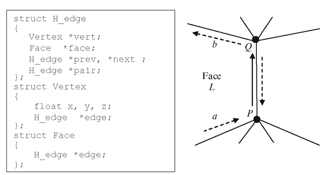
Fig. 8.13 The half-edge data structure
The half-edge data structure resolves the ambiguity by splitting every edge and storing it as two half-edges, each with a unique direction. A half-edge belongs to only a single face, which is the face on its left side. A half-edge structure stores references to the unique vertex the edge points to, the unique face it belongs to, the successor of the edge belonging to the same face, and the pair of the half-edge having the opposite direction and belonging to the adjacent face (Fig. 8.13). The half-edge structure is essentially a doubly linked list and hence is also known as the Doubly Connected Edge List (DCEL).
The components of the half-edge PQ in Fig. 8.13 are the references to the ending vertex Q, the face L on its left side, the next edge b on the same face, and the pair which is the half-edge QP in the opposite direction. Edge processing algorithms often use references to the previous edge (e.g., the method shown in Fig. 8.14), and this information may also be stored in the edge structure. As in the case of the winged-edge structure, two additional tables/structures are used to obtain a half-edge from either a vertex or a face. The vertex table contains for each vertex, its coordinates and a half-edge incident at that vertex. The face table contains for each face, a half-edge that belongs to that face. From the definition of the half-edge structure, it is clear that for a given half-edge edge, the end and start points are given by edge->vert, and edge->pair->vert respectively. Similarly, the two faces that border an edge are given by edge->face and edge->pair->face.
We will now consider the algorithm for computing all edges incident at a given vertex v. Using a half-edge data structure, the edges can be unambiguously retrieved using a simple iteration (Fig. 8.14). The modified version of the pseudo-code in Listing 8.2 using the half-edge data structure is given in Listing 8.5. In this case, the algorithm is simpler without any case distinction, and returns edges that end at the given vertex in anticlockwise order.
Fig. 8.14 Computation of incident edges at a vertex in anticlockwise and clockwise orders using the half-edge structure
Listing 8.5 Pseudo code for finding all edges that end at a vertex in anticlockwise order
Listing 8.6 Pseudo code for finding all faces adjacent to a face
In Listing 8.5, if we replace the output statement with output (edge->pair->vert), we get all the vertices in the one-ring neighbourhood of the given vertex. Likewise, the method with output(edge->face) returns all faces that share the vertex. The half-edge data structure provides a convenient tool for enumerating all faces that are adjacent to a given face (Listing 8.6).
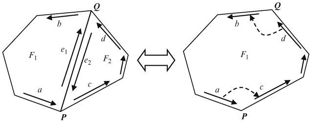
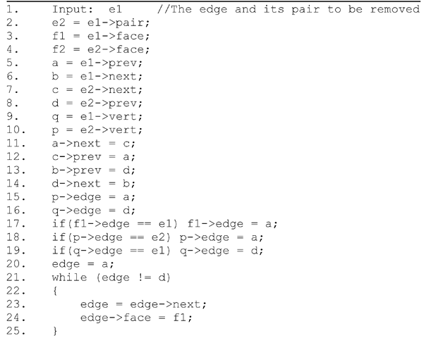
An edge data structure links together adjacency information pertaining to vertices, faces and neighbouring edges. The removal of an edge from a polygon calls for an update of this information by way of readjusting references to the deleted edge and adjacent faces. As an example, if the edge PQ of the polygonal face shown in Fig. 8.15 is removed, several edges along the boundary of the resulting polygon will need to be updated. Listing 8.7 provides the list of "tidy-up” operations required after removing PQ. Even though the edges marked ‘a\ ‘b’, V, ‘d’ in Fig. 8.15 can be indirectly referenced through either e1 or e2, separate variable declarations for each of these edges are used in Listing 8.7 for better clarity.
Fig. 8.15 Readjustments to pointers/references are required when an edge is removed
Listing 8.7 Pseudo code for finding all edges through a vertex in anticlockwise order
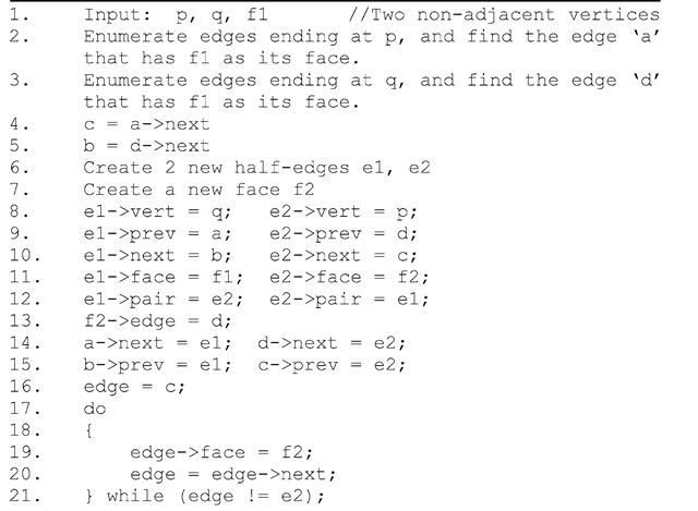
We now consider the inverse of the process discussed above, where a new edge is introduced into a polygon, splitting the polygon into two separate polygons. This process is commonly used for incrementally triangulating an arbitrary polygon. With reference to Fig. 8.15, the sequence of operations required for adding a new edge PQ is given in Listing 8.8.
In the following sections, we consider more complex mesh processing algorithms that use different types of adjacency information.
Listing 8.8 Procedure for adding a new edge PQ to a polygon
