Cyclic Coordinate Descent
The Cyclic Coordinate Descent (CCD) algorithm is a well-known method used for inverse kinematics solutions in computer graphics applications involving joint chains and moving targets. CCD performs a series of rotations on the links of a joint chain, starting with the last link, each time trying to move the end effector closer to the target.
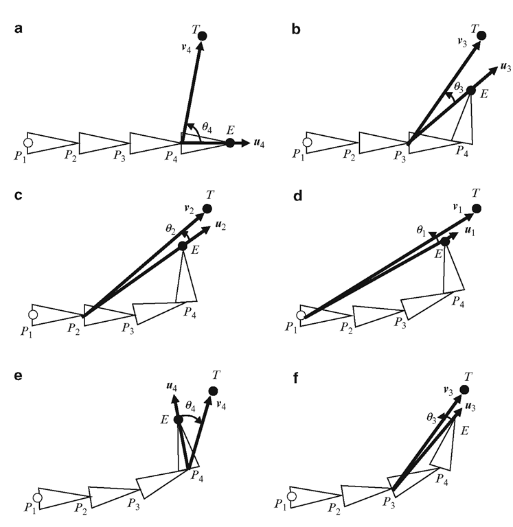
A sequence of rotations performed by the CCD algorithm for a 4-link chain on a two-dimensional plane is shown in Fig. 6.12. The joints of the links are denoted by P1, P2 … etc., the target by T, and the end effector position by E. The last link is rotated first by an angle 64 about P4, where 64 is the angle between end effector vector u4 = E — P4 and the target vector v4 = T — P4 (Fig. 6.12a).
Fig. 6.12 Sequence of rotations performed by CCD algorithm on a 4-link joint chain
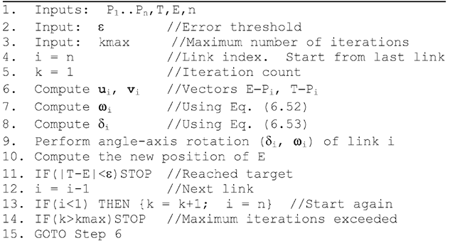
Listing 6.2 Pseudo code for the CCD algorithm
This rotation brings the end effector E to a point on the target vector. The second rotation is performed about the next link position P3, by an angle 63 between the end effector and target vectors at that point (Fig. 6.12b). This process of rotating links is continued till the first link P1 is reached (Fig. 6.12d), and then repeated over, starting again from the last link P4 (Fig. 6.12e). In three-dimensional space, the axis of rotation for the ith link at position Pi is calculated as
where ui = E — Pt, and vi = T — Pt. The angle of rotation about the unit vector !i is
The general algorithm for a n-link joint chain is given in Listing 6.2.
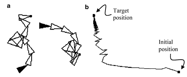
The terminating condition for the iterative algorithm can be defined based on the distance TE between the end effector and the target, and also the number of iterations performed. Physical systems using a set of joints, such as robotic manipulator arms, have joint angle constraints and other physical limitations that should be taken into account while designing an inverse kinematics solution. The CCD algorithm can generate large angle rotations that may violate joint angle constraints. In some cases, particularly when the target is located close to the base, the CCD algorithm causes a chain to form a loop, intersecting itself (Fig. 6.13a). Similarly, for certain target positions, the algorithm can take a large number of iterations resulting in a slow zigzag motion of the end effector (Fig. 6.13b). The method discussed in the next section is designed to overcome these drawbacks.
Fig. 6.13 (a) Two examples showing entangled configurations of a 10-link joint chain generated by the CCD algorithm. (b) The path showing the convergence of the end effector position towards a target location
Circular Alignment Algorithm
The circular alignment algorithm tries to place the given joint chain along a circular arc between the base and the target position, provided the target is reachable. With such a placement of the chain, joint angles will automatically assume values in an acceptable range, and there is no possibility of the chain to intersect itself. This method has some key advantages over the CCD algorithm:
1. This algorithm is significantly faster than the CCD algorithm. All joint angles have the same value based on a single solution.
2. The algorithm does not generate large angle rotations.
3. The algorithm does not generate entangled configurations of chains with large number of links.
The algorithm, however, requires all links to have the same length in order to use a simple inverse kinematics solution. The algorithm works on a two-dimensional plane containing the base of the link and the target. A general three-dimensional problem is thus reduced to two dimensions, assuming that the base link can be rotated in such a way that the whole chain is reoriented towards the target with all links constrained to move on a single plane. We will first consider the problem on the xy-plane, and later discuss how it could be generalized into three dimensions.
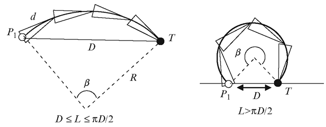
We assume that each link of an n-link chain has length d, and the total length of the chain is L = nd. The distance of the target T from the base P1 of the joint chain is denoted by D (Fig. 6.13). If the target is reachable (0 < D < L) then the joints of the link can be made to align along a circular path such that the end effector coincides with the target. There are two possible scenarios as shown in Fig. 6.13.
We first compute the angle ß subtended by the arc P1T, and then derive the radius, coordinates of the centre, and joint angle parameters from it. The angle ß is acute if the length L of the chain is less than nD/2, otherwise it is obtuse. In either case, we have
We seek the solution of the above equation for ß, by defining the function
The function has a derivative
The solution for ß can be obtained using Newton-Raphson iteration:
with the initial condition
The Newton-Raphson method yields fast convergence for the parameter ß, from which all joint angles can be computed as described below. The radius R of the circle and the perpendicular distance S (Fig. 6.15) can be obtained as
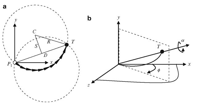
Without loss of generality, we can assume that the base of the link P1 is located at the origin of the coordinate system. If the target T has coordinates (xt, yt), the centre of the circle is selected among two possible values (Fig. 6.15) as
The above choice causes the chain to orient along an anticlockwise circular path towards the target, and to have positive values for the joint angles for both the cases shown in Fig. 6.14.
The joint angles for the two-dimensional case are computed as follows. The base link’s joint angle 61 is measured with respect to the x-axis, and is given by
Fig. 6.14 Circular alignment of joints
Fig. 6.15 (a) Two possible orientations of the joint chain for a given target position. (b) Extension of the inverse kinematics solution to three dimensions
All remaining joint angles have the same value given by
The approach detailed above can be extended to three dimensions where the target position is given by T = (xt, yt, zt). The problem is first reduced to two dimensions by transforming the target location to the xy-plane, and computing the joint angles as described previously. The transformed target position is
After computing the joint angles, the whole chain is rotated about the y-axis by an angle — ¢ as shown in Fig. 6.15b to achieve the desired configuration. The rotation angle ¢ can be computed as tan_1(zt/xt). This rotation can be combined with the joint angle rotation of the base link P1. We can add one more degree of freedom to the link by allowing the chain to rotate about the line joining the base and the target, thus varying the direction in which the end effector approaches the target.
Summary
This topic discussed forward and inverse kinematics equations for serial links containing only revolute or spherical joints. Such joint chains are commonly used in computer graphics for skeletal animation. Forward kinematics equations are used to compute the position of the end effector, given the joint angles. The topic presented methods for computing the linear velocity of the end effector as a function of angular velocities of the joints. Both Euler angle and quaternion based definitions of rotations were considered. In the most general case, when the end effector coordinates are expressed as functions of joint angles, the Jacobian matrix defines the relationship between the linear and angular velocities.
Inverse kinematics (IK) solutions can have singularities for redundant manipulators. The inverse Jacobian in the general IK solution is calculated in terms of the pseudo-inverse obtained using methods such as the singular value decomposition. If the distance between the end effector position and target is large, iterative numerical techniques are often used for a more accurate solution that converges to the target position. This topic also outlined the cyclic coordinate descent and the circular alignment algorithms that are useful for animating joint chains.
The next topic introduces parametrically generated curves and surfaces and discusses their applications in computer graphics.
![tmpc2f9-395_thumb[2][2][2] tmpc2f9-395_thumb[2][2][2]](http://what-when-how.com/wp-content/uploads/2012/07/tmpc2f9395_thumb222_thumb.png)
![tmpc2f9-396_thumb[2][2][2] tmpc2f9-396_thumb[2][2][2]](http://what-when-how.com/wp-content/uploads/2012/07/tmpc2f9396_thumb222_thumb.png)
![tmpc2f9-398_thumb[2][2][2] tmpc2f9-398_thumb[2][2][2]](http://what-when-how.com/wp-content/uploads/2012/07/tmpc2f9398_thumb222_thumb.png)
![tmpc2f9-399_thumb[2][2][2] tmpc2f9-399_thumb[2][2][2]](http://what-when-how.com/wp-content/uploads/2012/07/tmpc2f9399_thumb222_thumb.png)
![tmpc2f9-400_thumb[2][2][2] tmpc2f9-400_thumb[2][2][2]](http://what-when-how.com/wp-content/uploads/2012/07/tmpc2f9400_thumb222_thumb.png)
![tmpc2f9-401_thumb[2][2][2] tmpc2f9-401_thumb[2][2][2]](http://what-when-how.com/wp-content/uploads/2012/07/tmpc2f9401_thumb222_thumb.png)
![tmpc2f9-402_thumb[2][2][2] tmpc2f9-402_thumb[2][2][2]](http://what-when-how.com/wp-content/uploads/2012/07/tmpc2f9402_thumb222_thumb.png)
![tmpc2f9-403_thumb[2][2][2] tmpc2f9-403_thumb[2][2][2]](http://what-when-how.com/wp-content/uploads/2012/07/tmpc2f9403_thumb222_thumb.png)
![tmpc2f9-404_thumb[2][2][2] tmpc2f9-404_thumb[2][2][2]](http://what-when-how.com/wp-content/uploads/2012/07/tmpc2f9404_thumb222_thumb.png)
![tmpc2f9-407_thumb[2][2][2] tmpc2f9-407_thumb[2][2][2]](http://what-when-how.com/wp-content/uploads/2012/07/tmpc2f9407_thumb222_thumb.png)
![tmpc2f9-409_thumb[2][2][2] tmpc2f9-409_thumb[2][2][2]](http://what-when-how.com/wp-content/uploads/2012/07/tmpc2f9409_thumb222_thumb.png)
