The Jacobian
In general, we can assume that the end effector position E = (xe, ye, ze) of an n-link joint chain can be expressed as a function of joint angles 9, for , = 1,..,n, (for example, see Eq. 6.1). Thus we can write
If A9, denotes an infinitesimal change in the joint angles 9, for , = 1,..,n, and![]() the corresponding change in the end effector position during a small time interval At, we have,
the corresponding change in the end effector position during a small time interval At, we have,
Assuming that joint angle perturbations are small, we can use Taylor’s first order approximation to express the above set of equations in matrix form as follows:
From the above equation, it follows that
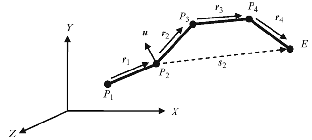
Fig. 6.8 The Jacobian matrix can be constructed using the axis of rotation of each link and a vector from that link to the end effector
where
The 3 x n matrix J is called the Jacobian of the transformation in Eq. 6.31.
As an example, consider the end effector position of a 3-link chain given in Eq. 6.1. The Jacobian in this case is a 2 x 3 matrix containing the partial derivatives of xe and ye with respect to the three joint angles. It can be easily verified that the expressions for the velocity components obtained using Eq. 6.34 are the same as those given in Eq. 6.17.
The ith column of the Jacobian in Eq. 6.33 can also be obtained using the axis of rotation of the ith link and the vector from that link to the end effector. Figure 6.8 shows an example, where the second link’s general rotational transformation has an equivalent axis of rotation given by the unit vector u. The vector from the second link to the end effector is E — P2 denoted by s2.
The second column of the 3 x 4 Jacobian matrix for the above example can be computed using the vector cross product u x s2. Note that s2 = r2 + r3 + r4.
Inverse Kinematics
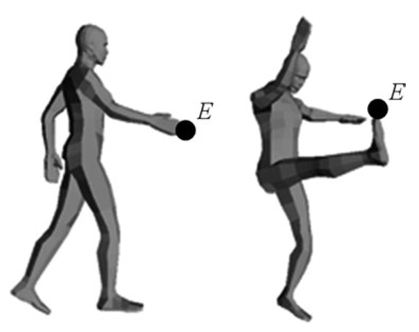
Inverse kinematics (IK) deals with the process of computing the joint angles, given the world coordinates of the end effector. Inverse kinematics solutions are needed for animating an articulated figure using only the desired positions of end points as inputs. Two examples are shown in Fig. 6.9, where the known end effector position is indicated by the point E.
Fig. 6.9 Inverse kinematics solutions try to find the joint angles of a serial chain given the position of the end effector
Fig. 6.10 (a) Multiple solutions may exist for the inverse kinematics problem for a 2-link chain. (b) A solution exists only when the target point is between the inner and outer circles. (c) A simple geometric construction used for an inverse kinematics solution
In the absence of joint angle constraints, multiple solutions may exist for a two link joint chain as shown in Fig. 6.10a. On the other hand, a solution may not exist for certain other positions of the end effector. In Fig. 6.10b, a solution cannot be found if the target position is either inside the inner circle of radius d1 — d2, or outside the outer circle of radius d1 + d2.
Without loss of generality, we can assume that the base of the joint chain A is fixed at the origin. We can also assume that there are no joint angle constraints. In the following sections, we will discuss methods for arriving at inverse kinematics solutions with these assumptions.
2-Link Inverse Kinematics
We can easily develop an analytical solution for the 2-link inverse kinematics problem for the configuration shown in Fig. 6.10c. If the coordinates (xe, ye) of the end point E are given, the joint angles 91, 92 can be determined as follows:
Let AE = k. Therefore, k2 = xe2 + ye2. From triangle ABE we get,
Hence,
Also,
From triangle AEE0,
From the previous two equations, we get
Equation 6.37 is valid only if
The above condition corresponds to the situation shown in Fig. 6.10b.
n-Link Inverse Kinematics
For a general n-link configuration, the problem of estimating the joint angles 61; 62, …, 6n, given only the end effector coordinates (xe, ye, ze), clearly leads to an under-determined system of equations when n > 3. Such a system is called a redundant manipulator, implying that more than one set of joint angles could possibly lead to the same end effector position. A non-redundant manipulator in three-dimensional space contains only three links.
Suppose we are required to move the end effector from its current position E to a desired target location given by T = (xt, yt, zt). The inverse kinematics problem can be rephrased as follows: Determine the change in joint angles required to produce a change in the end effector position from E to T. If we denote this displacement of the end effector by the vector AE = T — E, and the joint angle perturbation vector by A0, then from Eq. 6.33 we know that
where J is the 3 x n Jacobian matrix. J is invertible only for a non-redundant manipulator (n = 3). Generally when n > 3, J is not a square invertible matrix, and therefore we cannot directly obtain A0 from the above equation. However, premultiplying both sides by the transpose JT, we can form a symmetric, square and invertible matrix (JTJ), and then obtain a solution for A0 as
where
The above matrix is called the left pseudo-inverse of J. For an n-link chain, (JTJ) is an n x n matrix. One could use Singular Value Decomposition (SVD) to compute the pseudo-inverse of J. If J has a decomposition of the form USVT, then the pseudo-inverse of J is given by
In the above matrix equation, U is a 3 x 3 orthogonal matrix, S is a 3 x n diagonal matrix, and V is a n x n orthogonal matrix. Columns of U are orthonormal eigenvectors of JJT, and the columns of V are orthonormal eigenvectors of JTJ. The matrix S contains square-roots of eigenvalues of either JJT or JTJ. Its inverse SC can be readily obtained by transposing S and taking the reciprocals of the diagonal elements. Denoting the columns of U by vectors u, (, = 1..3), and the columns of V by vectors v, (, = 1..n), we have
and
where ai denotes the ith eigenvalue of the square matrix JJT, and![tmpc2f9-385_thumb[2][2] tmpc2f9-385_thumb[2][2]](http://what-when-how.com/wp-content/uploads/2012/07/tmpc2f9385_thumb22_thumb.png) Substituting the above expression in Eq. 6.43 and simplifying,
Substituting the above expression in Eq. 6.43 and simplifying,
Note that the sizes of the three matrices on the right-hand side of the above equation are n x 3, 3 x 3, and 3 x 1 respectively. In the following sections, we discuss iterative numerical methods that try to move the end effector through a sequence of points to the desired target position.
Gradient Descent
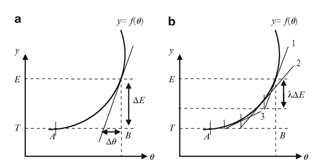
The inverse kinematics solution for computing A0 as outlined in the previous section is based on an important assumption that both AE (the distance from the current end effector position to the target) and A0 (joint angle perturbations) are small. Many practical situations violate these conditions. The two-dimensional analogue of the situation where the distance between the end effector and target is large is shown in Fig. 6.11a. The y-axis represents the end effector position whose dependency on the joint angle 6 is given by the function y = f (6 ). The desired target position is indicated by the ordinate T.
Fig. 6.11 (a) Computing AO from the derivative alone can lead to significant errors if AE is large. (b) The iterative convergence of the gradient descent algorithm
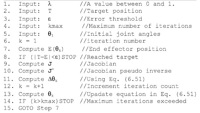
Listing 6.1 Pseudo code for the gradient descent algorithm
The solution given in Eq. 6.43 is equivalent to computing A9 in the above example using the formula
As can be seen from Fig. 6.11a, there is a large error in the value obtained for A 9, the solution giving only a fraction of the required change in 9 given by the distance AB. If AE is large, we will need to approach the target in smaller steps. This is done by scaling AE by a factor X (0 <X< 1), each time updating the end effector position and the derivative. This approach is called the gradient descent method, and is shown in Fig. 6.11b. The following equation computes the value of incremental changes in 9 for each iteration step k, and updates the function value and its derivative.
We can employ the gradient descent method for iteratively computing A0 after introducing the scaling factor X in Eq. 6.43. The modified equation is given below.
where 0k is a column vector of joint angles updated in the kth iteration. The gradient descent algorithm for computing the joint angles for a n-link chain is given in Listing 6.1.
![tmpc2f9-363_thumb[2]_thumb tmpc2f9-363_thumb[2]_thumb](http://what-when-how.com/wp-content/uploads/2012/07/tmpc2f9363_thumb2_thumb_thumb.png)
![tmpc2f9-366_thumb[2]_thumb tmpc2f9-366_thumb[2]_thumb](http://what-when-how.com/wp-content/uploads/2012/07/tmpc2f9366_thumb2_thumb_thumb.png)
![tmpc2f9-367_thumb[2]_thumb tmpc2f9-367_thumb[2]_thumb](http://what-when-how.com/wp-content/uploads/2012/07/tmpc2f9367_thumb2_thumb_thumb.png)
![tmpc2f9-368_thumb[2]_thumb tmpc2f9-368_thumb[2]_thumb](http://what-when-how.com/wp-content/uploads/2012/07/tmpc2f9368_thumb2_thumb_thumb.png)

![tmpc2f9-370_thumb[2]_thumb tmpc2f9-370_thumb[2]_thumb](http://what-when-how.com/wp-content/uploads/2012/07/tmpc2f9370_thumb2_thumb_thumb.png)


![tmpc2f9-374_thumb[2][2] tmpc2f9-374_thumb[2][2]](http://what-when-how.com/wp-content/uploads/2012/07/tmpc2f9374_thumb22_thumb.png)
![tmpc2f9-375_thumb[2][2] tmpc2f9-375_thumb[2][2]](http://what-when-how.com/wp-content/uploads/2012/07/tmpc2f9375_thumb22_thumb.png)
![tmpc2f9-376_thumb[2][2] tmpc2f9-376_thumb[2][2]](http://what-when-how.com/wp-content/uploads/2012/07/tmpc2f9376_thumb22_thumb.png)
![tmpc2f9-377_thumb[2][2] tmpc2f9-377_thumb[2][2]](http://what-when-how.com/wp-content/uploads/2012/07/tmpc2f9377_thumb22_thumb.png)
![tmpc2f9-379_thumb[2][2] tmpc2f9-379_thumb[2][2]](http://what-when-how.com/wp-content/uploads/2012/07/tmpc2f9379_thumb22_thumb.png)
![tmpc2f9-380_thumb[2][2] tmpc2f9-380_thumb[2][2]](http://what-when-how.com/wp-content/uploads/2012/07/tmpc2f9380_thumb22_thumb.png)
![tmpc2f9-381_thumb[2][2] tmpc2f9-381_thumb[2][2]](http://what-when-how.com/wp-content/uploads/2012/07/tmpc2f9381_thumb22_thumb.png)
![tmpc2f9-382_thumb[2][2] tmpc2f9-382_thumb[2][2]](http://what-when-how.com/wp-content/uploads/2012/07/tmpc2f9382_thumb22_thumb.png)
![tmpc2f9-383_thumb[2][2] tmpc2f9-383_thumb[2][2]](http://what-when-how.com/wp-content/uploads/2012/07/tmpc2f9383_thumb22_thumb.png)
![tmpc2f9-384_thumb[2][2] tmpc2f9-384_thumb[2][2]](http://what-when-how.com/wp-content/uploads/2012/07/tmpc2f9384_thumb22_thumb.png)
![tmpc2f9-387_thumb[2][2] tmpc2f9-387_thumb[2][2]](http://what-when-how.com/wp-content/uploads/2012/07/tmpc2f9387_thumb22_thumb.png)


![tmpc2f9-390_thumb[2][2] tmpc2f9-390_thumb[2][2]](http://what-when-how.com/wp-content/uploads/2012/07/tmpc2f9390_thumb22_thumb.png)
![tmpc2f9-391_thumb[2][2] tmpc2f9-391_thumb[2][2]](http://what-when-how.com/wp-content/uploads/2012/07/tmpc2f9391_thumb22_thumb.png)
![tmpc2f9-392_thumb[2][2] tmpc2f9-392_thumb[2][2]](http://what-when-how.com/wp-content/uploads/2012/07/tmpc2f9392_thumb22_thumb.png)
