Bounding Volume Hierarchies
Bounding volume hierarchies (BVH) were briefly introduced in Sect. 3.4 in the context of scene graphs. Using a BVH, the space enclosed by a collection of objects that are located close to each other in a scene can be hierarchically represented in terms of bounding volumes of subgroups within the collection, with the leaf nodes containing sufficiently small object parts and optionally their bounding volumes. In this representation, a parent node stores the combined bounding volume of a set of objects in the child nodes. A bounding volume for a single complex mesh object may also be subdivided into groups of bounding volumes of smaller components or parts of the mesh. A bounding volume hierarchy can therefore be viewed as a multi-scale representation of an object using bounding volumes. The hierarchical tree structure of bounding volumes is useful in significantly reducing the amount of pair-wise overlap tests. Bounding volume overlap tests are performed from the root of the tree to determine if the overall bounding volume intersects another primitive or another bounding volume. If the intersection test fails at this point, further tests using smaller sub-volumes stored in child nodes are not carried out. The complexity of intersection tests can thus be reduced using a well designed hierarchy. Some of the design considerations are
• the efficiency and speed of computing the bounding volume parameters
• the optimality of the computed bounding volumes
• the amount of overlap between bounding volumes of sibling nodes
• the frequency of updates
The following two sections describe commonly used strategies for the construction and traversal of bounding volume hierarchies.
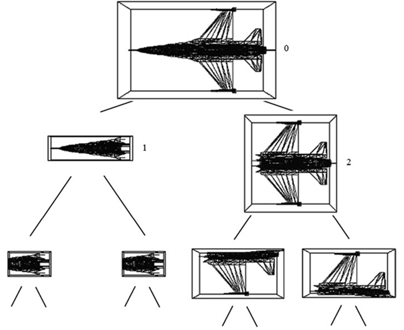
Fig. 9.19 A bounding volume hierarchy using AABBs formed using top-down construction
Top-Down Design
The top-down construction of a bounding volume hierarchy starts with the formation of the bounding volume of an object, then recursively subdivides the mesh object into two nearly equal parts and stores their bounding volumes in the child nodes. The partitioning of the mesh is usually done by axis aligned splitting planes. Mesh primitives are assigned to either the left or the right child node based on the location of their centroids with respect to the splitting plane of the current node. The bounding volumes of the mesh sections stored in the child nodes are then computed. This process is repeated until a maximum level for the binary tree is reached, or until a node contains only a sufficiently small number of primitives.
A bounding volume hierarchy constructed using AABB in the top-down fashion is shown in Fig. 9.19. At each node, the longest axis of the AABB is chosen, and the plane perpendicular to this axis passing through the centre of the AABB is selected as the splitting plane. For example, if the AABB is given by its mid point (xmid, ymid, zmid) and the three half-width extents xr, yr, zr, and if xr > yr, and xr > zr, then the plane parallel to the yz-plane through the midpoint is chosen as the splitting plane.
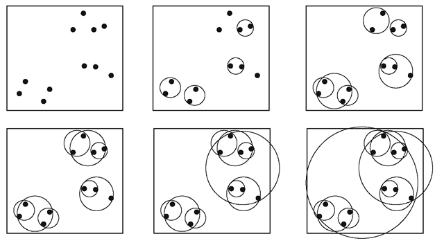
Fig. 9.20 An agglomerative clustering algorithm forms small cluster groups and merges them recursively based on pair-wise distances between existing clusters
The triangles of the mesh whose centres have the x-coordinate less than xmid are assigned to the left child, and the remaining triangles to the right child. In Fig. 9.19, the yz-plane was chosen as the splitting plane at nodes 0 and 1, and the xz-plane at node 2.
The top-down approach is particularly suitable for run-time construction of bounding volume hierarchies of large mesh objects using simple mesh partitioning strategies as outlined above. Therefore, most of the BVH algorithms use this method.
Bottom-Up Design
The bottom-up design approach is suitable for creating bounding volume hierarchies of a group of small objects that are located near each other. The construction of the tree starts with the bounding volumes of each object in the group which are then combined pair-wise, based on a distance measure. The bounding volume of the combined object is recomputed. This process is repeated until the bounding volume of the entire group is constructed at the root node. It is easy to see that methods like this run in parallel with agglomerative (bottom-up) hierarchical clustering algorithms that use pair-wise distances to form larger and larger groups of objects (Fig. 9.20).
The bottom-up construction has the advantage that the bounding volume updates at a parent node can be done by simply merging together the bounding volumes of the child nodes. Vertex data for objects or primitives stored in the leaf nodes therefore need not be copied to the parent nodes. This mechanism is ideally suited for a scene graph based implementation where object data is stored only in leaf nodes (see Sect. 3.4). The main drawback of this approach is that the merged volume may not be the minimal volume for geometries such as the sphere (see Fig. 3.15). For AABBs and k-DOPs however, merging two minimal volumes does yield a minimal volume. Accurate computation of bounding volume requires merged primitive/object information also to be stored at internal nodes. Some of the commonly used methods for computing the parameters of the merged bounding volumes are discussed below.
The equations for computing the parameters of a sphere formed by merging together two spheres were given in Eq. 3.3. Merging two OBBs is done by collecting the vertices (Eq. 9.29) of both OBBs and computing a new OBB for these 16 points using the methods outlined in Sect. 9.1.3.
Two k-DOPs can be easily merged if they share the same set of normal vectors. The method is exactly the same as that used for AABBs. If the k-DOPs are given by {dminj(X), dmaxj(V), nj}, {dminj(2), dmax/2), nj}, j = 0 ••• (k/2)—1, then the combined volume is {dmnj, dmxj, nj}, where dmnj = min(dminj(1), dminji2)) and dmxj = max(dmaxj(1), dmaxj(2) ), for all j.
Collision Testing Using Hierarchy Traversal
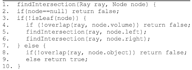
Collision between a primitive (e.g., a ray) and an object (or a group of objects) can be detected by traversing the bounding volume hierarchy of the object(s) from the root node in a recursive manner. At each step, an overlap test is performed by comparing the bounding volume stored at a node of the tree with the primitive. Such a method is useful in reducing the number of ray-object intersection tests in ray tracing algorithms and also in games, where for instance, a ray represents the direction of flight of a bullet. A recursive ray intersection algorithm is given as a pseudo code in Listing 9.2. In this code, node.volume represents a structure that stores bounding volume parameters at a node, and overlap() is a method that tests if the given ray intersects the volume. At a leaf node, the ray is tested with the object primitive stored at that node.
Listing 9.2 Ray-object intersection testing using a BVH
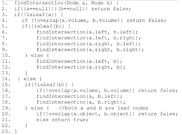
Listing 9.3 Collision testing using two BVHs (Simultaneous descent)
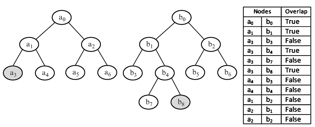
Object-object intersection tests can be done using their respective bounding volume hierarchies. This process will require a systematic procedure that specifies how the trees must be traversed. A commonly used technique is to descend both hierarchies simultaneously using a depth-first approach. If the objects represented by the hierarchies intersect, the recursion will terminate at the leaf nodes of both trees. A pseudo-code for the method is given in Listing 9.3. In this code, node ‘a’ belongs to the first tree, and ‘b’ belongs to the second tree. The procedure is called by passing the root nodes of the trees as parameters. It is assumed that the leaf nodes contain both primitive data (e.g., vertices of a triangle) as well as the bounding volume.
An example showing two binary trees and the sequence of node comparisons used by the above method is given in Fig. 9.21. In this example, the primitives at nodes a3 and b8 intersect.
Fig. 9.21 An example showing the simultaneous descend of two bounding volume hierarchies
Cost Function
The evaluation of the performance of a BVH-based method for collision detection is usually done with the help of a cost function. There are primarily three types of important operations performed:
• Bounding volume updates are often required when the object undergoes translational and rotational transformations.
• Bounding volume overlap tests are performed when an internal node of a BVH is compared with an internal node of another BVH.
• Primitive intersection tests are performed at the leaf nodes of a bounding volume hierarchy.
The cost function is the aggregate of the costs for each of the above operations, and is defined as
where Cu is the average cost of updating a bounding volume, nu the number of bounding volumes updated, Cv the average cost of testing if a pair of bounding volumes overlap, nv the number of bounding volume overlap tests performed, Cp is average cost of testing if a pair of primitives intersect, and np the number of primitive intersection tests performed. The value of nv will be large if several bounding volume overlap tests are done at internal nodes even when the primitives at the leaves do not intersect. Therefore, selecting a tight fitting bounding volume for the construction of the BVH helps in bringing down the value of nv. However, tight fitting bounding volumes such as convex hulls generally have a higher value of Cv compared to AABBs and spheres. Reducing the number of internal nodes results in a reduction in nu. The cost functions Cu, Cv, and Cp may be defined based on the number of geometrical computations such as vector products involved in each operation.
Spatial Partitioning
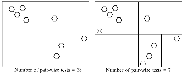
In this section, we will look at some of the important spatial partitioning tree structures useful for collision detection. If a scene consists of n objects that can move and potentially collide with each other, the number of pair-wise tests required is n(n—1)/2. Spatial partitioning techniques help to subdivide the entire three-dimensional space occupied by the objects into a set of regions. Using such techniques we can quickly determine if objects in a group are not likely to intersect objects in another group (because they belong to disjoint regions), and thus eliminate the need for performing pair-wise tests between members of the two groups. A region based grouping of objects such that a member within any group is guaranteed not to intersect any member belonging to any of the other groups is called broad-phase collision detection. The grouping also suggests that objects within the same group may potentially collide. Pair-wise intersection tests using methods discussed in the previous section are used only to detect collision between objects within each group. Pair-wise tests using both bounding volumes and primitives are collectively called the narrow phase collision detection methods. Figure 9.22 provides an example showing the reduction in pair-wise tests achieved by a grid-based partitioning of the space into disjoint regions.
Octrees
An octree defines a regular partitioning of an axis-aligned cube into eight equally sized sub-cubes (octants) by dividing the cube by half along each of the axis. Each sub-cube is again divided into eight sub-cubes in a similar manner. The process of recursively subdividing the cube continues until a pre-specified maximum for the depth of the tree has been reached, or the cube size has become smaller than a pre-specified minimum value. If the number of primitives within a cube is less than a threshold value, and in particular, if a cube is empty, it is not subdivided further. The initial cube encloses the whole three-dimensional space occupied by the objects, and forms the root node of the octree. Each internal node of an octree has exactly eight children corresponding to the sub-cubes of the parent node. A node is subdivided only when necessary.
Fig. 9.22 An example showing the reduction in the number of pair-wise tests using spatial partitioning
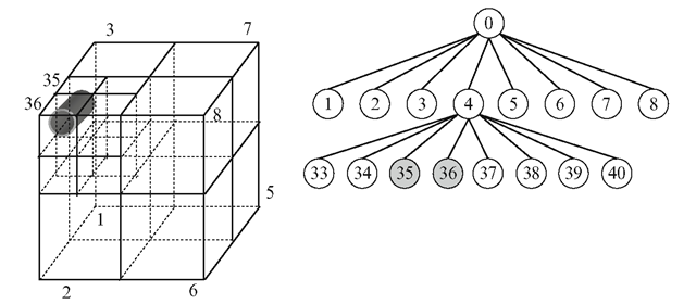
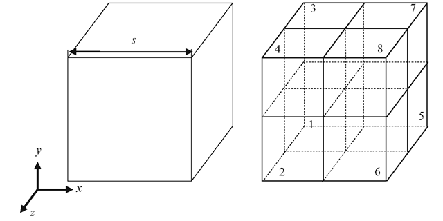
Fig. 9.23 A subdivision of a cube into octants. Cube indices are assigned based on the positions of the sub-cubes relative to the midpoint of the parent
The geometrical information about a cube is stored in terms of the position of its midpoint and size. Each cube is also assigned a unique index (Fig. 9.23). The root node has index 0, and its children have indices 1-8. We use the notation i:(xc, yc, zc, s) to denote the cube with index i, centre (xc, yc, zc) and side length s. When the cube is subdivided into eight octants, its children are stored as follows:
Using the above index representation, a node among a group of child nodes has an index k = 8i + j, j = 1..8. The parent’s index i can be obtained from k using the integer division (k—1)/8. Applying the transformation b = (k —1) mod 8, we get a value between 0 and 7 which can be represented using 3 bits.
Fig. 9.24 Space partitioning using octrees
If the lowermost bit of b is 1, it indicates that the node is located towards the positive z direction from its parent. A bit value 0 indicates that the node is in negative z direction. The middle bit similarly gives the node’s relative location along y direction (1: positive, 0: negative). The highest bit gives the x-direction. As an example, if a node’s index is 30, its parent has the index 3, and b = 5 (=101 binary). The x and z coordinates of the node’s centre are greater than that of its parent, while the y-coordinate is less. We can also use the index information to compute the bounding planes of a cube. Every cube except the root is bounded on three sides by axis-aligned splitting planes through the centre of its parent. These planes are x = xc, y = yc, z = zc, where (xc, yc, zc) is the midpoint of the parent cube. The remaining three bounding planes are given by the bit values of b. For the example given above, where b has a binary value 101, the three remaining bounding planes are x = xc + (s/2), y = yc — (s/2) and z = zc + (s/2). Note that s is the size of the parent, not the sub-cube under consideration. A cube’s six bounding planes can also be directly obtained from its own centre and size, but the former method uses three common planes for every child of a given parent node, and requires only three additional planes for each child.
Figure 9.24 shows the subdivision of a three-dimensional volume containing a cylindrical object. The indexing of this volume using an octree is also shown in the figure. The initial volume is divided into eight octants as the volume is non-empty. In the next step, the non-empty volume with index 4 is further subdivided into eight octants. The indices of the children of node 4 have values from 33 to 40 (8*4 + j, j = 1..8). The object intersects the sub-cubes 35 and 36, and is therefore included in both these nodes. Further subdivision of these nodes is likely to produce intersection of the object with all sub-cubes, and therefore may not be carried out.
A top-down traversal of the octree from the root node is often performed to locate the smallest cube of the tree that contains a given point P = (xp, yp, zp). If the current node is i:(xc, yc, zc, s), we can identify the next node containing P using its index k computed as given in Listing 9.4.
Listing 9.4 Computation of the index of a child node that contains a point P
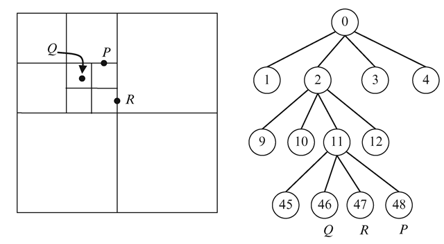
Fig. 9.25 An example showing quadtree subdivision and traversal
The two-dimensional equivalent of an octree is called a quadtree. A quadtree represents subdivisions of a square using four child nodes. For a quadtree, the computation of the index k in Listing 9.4 will use only the x and y coordinates. The corresponding formula for the index of the child node is k = 4*i + 2*b1 + b2 + 1. A group of four child nodes will thus have indices of the form 4i + j (j = 1..4). The position of a square relative to its parent is south-west if j = 1, north-west if j = 2, south-east if j = 3, and north-east if j = 4. This subdivision scheme establishes the method for quadtree descent, illustrated in Fig. 9.25. Note that a point on a vertical splitting line gets assigned to the square on its left, and a point on a horizontal splitting line gets assigned to the square below it. Note also that empty squares are not subdivided further. A similar traversal algorithm can be formulated for an octree.
We now use the octree traversal algorithm for finding the leaf nodes where a three-dimensional object is stored (as in Fig. 9.24). The object is stored in every leaf node it overlaps. To simplify the problem, we use the AABB of the object given in terms of the parameters {xmin, xmax, ymin, ymax, zmin, zmax}. We descend the octree using the points P = (xmin, ymin, zmin) and Q = (xmax, ymax, zmax) as discussed in the previous paragraph, and find the lowest node containing both P and Q. This internal node represents the minimum volume of the subdivision that contains the entire AABB, and hence the entire object. The children of this node are recursively examined to check if any of the sub-cubes overlap the given AABB. Since a cube itself is an AABB, we can use the AABB intersection test in Sect. 9.2.1 for this purpose. If a node does not overlap the given AABB, its children need not be tested. This process is repeated until we reach the leaf nodes and return the indices of those leaf nodes that overlap the AABB. This information is vital for the broad-phase collision detection of the object. The object can potentially intersect only other objects or primitives stored at these leaf nodes.
A bounding sphere enclosing an object can also be stored in an octree using a procedure similar to that described above. An octree node i:(xc, yc, zc, s) overlaps a bounding sphere with centre at position p = (xp, yp, zp) and radius r if and only if the distance between the centre of the sphere and the centre of node (cube) is less than or equal to the radius of the sphere. To avoid the square-root computation, this condition is usually expressed as follows:
In the next section, we will look at a recursive binary partitioning tree that is comparatively easier to traverse than an octree.
![tmpf9b3-192_thumb[2][2][2][2] tmpf9b3-192_thumb[2][2][2][2]](http://what-when-how.com/wp-content/uploads/2012/07/tmpf9b3192_thumb2222_thumb.png)
![tmpf9b3-195_thumb[2][2][2][2] tmpf9b3-195_thumb[2][2][2][2]](http://what-when-how.com/wp-content/uploads/2012/07/tmpf9b3195_thumb2222_thumb.png)
