Galileo Signal Generator
In order to further study the Galileo signals, we have implemented a simple signal simulator in Simulink.
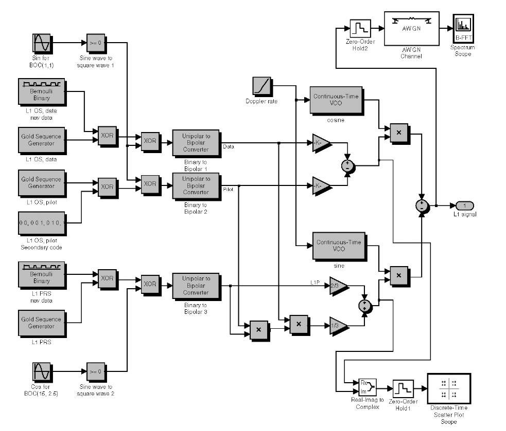
Figure B.5 shows the Simulink model of the Galileo signal simulator. The present version is made of standard Simulink blocks, and it does not have any custom blocks (called subsystems in Simulink). The gray blocks in the model are part of the generator, and the white blocks are used to visualize the generated signal. The white blocks do not contribute in any way to the signal generation. The generator directly implements the BOC, CASM, and other steps described earlier in this topic. It is easy to see CASM constants and math operations in the model that correspond to (3.2)-(3.4).
FIGURE B.5. The Simulink model that generates the L1 signal. The gray blocks generate the Galileo signal, and the white blocks are used to visualize the signal.
The model can be divided into three parts from left to right (excluding the white blocks). The first part consists of the generators of PRN, BOC signal, and random bits of navigation messages. This is the left part of the model. It makes all three navigation signals at the baseband (from the top to the bottom): data channel, pilot channel, and restricted access channel.
The center part of the diagram converts binary signals of the left side to bipolar ±1 signals. Simulink PRN generators are generating binary data and the bipolar signals are required for the CASM algorithm.
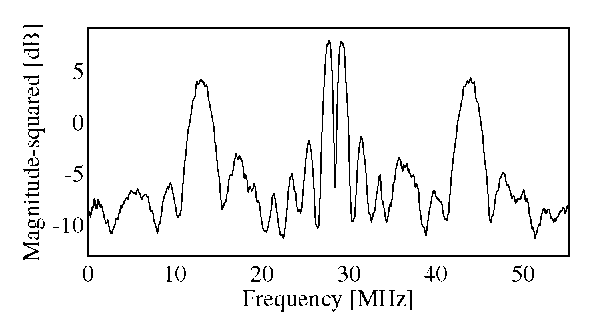
The CASM part is implemented on the right side of the model. The output of the model is Galileo L1 signal at theL1 frequency. The zero-order hold blocks are used to sample continuous signal. The sampling frequency is 110.5 MHz, and the result of sampling the IF is about 28 MHz. The signal spectrum after sampling is shown in Figure B.6. It clearly shows the two main lobes of BOC(1,1) at the center of the spectrum. The two OS signals are sharing this part of the spectrum. The two wide lobes at the sides of the spectrum originate from the restricted access signal BOC(15,2.5).
FIGURE B.6. Spectrum for generated Galileo L1 signal.
Our model does not save the signal from the generator. The output of the generator must be sampled and directed to a file or a variable in MATLAB workspace. The technique is similar to the implementation of the FFT plot visible at the top right corner of the diagram. A zero-order hold block is needed to sample the signal. Then one of the signal sinks must be inserted from the Simulink block library depending on whether it has to be a file or a variable. The Additive White Gaussian Noise (AWGN) block is used to add noise to the signal.
The current model only generates the signal for one satellite at a time. It can be used as a subsystem in Simulink. So several such generators must be connected to generate signals of a constellation of satellites. Section B.2.5 describes how that can be implemented.
The current model is very basic and must be updated comprehensively in order to account for properties and propagation environment of the real signals. First a more complicated signal propagation model must be added which accounts for signal amplification at the satellite, signal losses in free space, atmosphere, antennas, and the front end. Next the model must be modified to include Doppler effects. The rate of all generators (data, PRN, subcarriers, and the carrier) must be controlled simultaneously and all intersignal phases must be preserved. This requires custom implementations of these blocks. An excellent example of an advanced generator is explained in the Mathworks webinar "Implementing a GPS Receiver with DSP and FPGA Hardware Using Simulink and Related Tools."
Differences in Processing GPS and Galileo Signals
Originally this text was planned to deal with both GPS and Galileo on equal terms. It soon became clear that this ideal goal had to be modified. It turned out to be difficult to get reliable detailed information about Galileo signals; in addition, the necessary testing of the software implementation also became difficult to carry out.
We therefore decided to list the differences between GPS and Galileo signals and next mention how to deal with them in a future software implementation.
Signal Differences
This listing only considers Galileo L1 OS and GPS C/A on L1. First the signal differences are analyzed. The following paragraphs outline the differences in the receiver signal processing.
Signal Types GPS has one public signal and one encrypted, restricted access signal. Galileo will have three signals: two public signals, called Open Service (OS) signals, and one encrypted, called a Public Regulated Service (PRS) signal. Only the OS signals will be considered in the following. One of the OS signals, the data channel, will contain navigation data (ephemerides, almanac, and additional information). The pilot channel will not be modulated with navigation data. It will only be modulated with a short sequence of bits (a secondary code with a code length of 25 chips), which will be repeated all times.
Spreading Codes GPS uses a spreading code with 1023 chips, whereas Galileo will use spreading codes with lengths of 4096 chips. The chipping rate is the same for GPS and the Galileo OS signals, 1.023 MHz, but all Galileo codes on L1 are combined with a subcarrier signal (BOC signals). The subcarrier rate is 1.023 MHz for both the L1 OS data and pilot signals. It is expected that a similar type of signal will be used in the modernized GPS (most likely by the GPS III program). The transmitted GPS L1 signals are bandwidth limited to 20 x 1.023 MHz whereas the Galileo L1 signals are limited to 40 x 1.023 MHz.
The Galileo PRN codes are not yet published. Depending on the final choice of codes, two techniques exist to generate the PRN codes. One is to use linear feedback shift register generators similar to those used in GPS, but with longer registers. The second is to use memory codes that may be pregener-ated and stored in memory.
Recent Galileo signal developments indicate that additional codes may be used on top of BOC coding to improve signal properties and signal tracking performance; see Hein et al. (2005).
Data Modulation The data modulation process is the same in GPS and Galileo. The BOC signal is multiplied by the data signal (the XOR operation is the equivalent for binary logic signals). The pilot signal is using the same technique to modulate the BOC signal by the secondary code. The navigation data rate on the data channel is 250 Hz. It is likely that the data rate of the secondary code on the pilot channel will be similar to this.
Data Structure The Galileo system will use a superframe, frame, subframe construction similar to GPS. Subframes will have a unique word facilitate synchronization to the start of the subframe (similar to the preamble in GPS). The unique synchronization word is followed by the data part, a checksum field, and tail bits. It is expected that the construction of the data part will be different from that of the GPS messages.
Ephemerides and Almanac The satellite orbit parameters have the same field size and scale in both systems. The time parameters have different field size and scales (except clock correction coefficients in the almanac).
Synchronization Word (Preamble) GPS is using an 8-bit (symbol) pattern. Galileo is likely to use a 10-symbol pattern.
Error Detection Galileo will use cyclic redundancy check (CRC) to detect data corruptions inside subframes. It is expected that the CRC will be computed over the 24 data bits in the subframe. The specification does not indicate that any bits from the previous subframe should be used in computation of the CRC.
Channel Coding In addition to CRC, Galileo will use forward error correction (FEC) to detect data corruptions and correct corruptions to a certain extent. This will facilitate correction of a much larger amount of corruptions compared to GPS where only one bit per subframe can be corrected. Block interleaving will be used to make the Galileo data even more corruption resistant.
FEC is used already in WAAS and EGNOS signals.
Data Authentication Galileo is likely to use a data authentication technique to make the GNSS signal tracking secure. The purpose of the data authentication is to provide means for the user to distinguish genuine Galileo signals from simulated signals (the technical term is signal spoofing). Signal spoofing is an intentional malicious provision of faulty signals that can lead to malicious location spoofing.
Only certified receivers will be able to decode authentication information, but the authentication will be provided by the OS signals. P(Y) code encryption is the means of signal authentication in GPS.
Modulation Galileo uses BOC(1,1) modulation (which in effect perform manchester encoding of the data and pilot channel) and the CASM multiplexing scheme to combine three signals into a hexaphase representation whereas GPS uses BPSK.
Time Reference Galileo will use a reference time called Galileo System Time (GST) whereas GPS uses GPS Time (GPST). GPS Time is a composite clock; the average of a number of GPS clocks computed in a Kalman filter. Galileo System Time is a master clock; the output of a steered active H-maser. Galileo System Time will be steered to International Atomic Time (TAI) at the Galileo Precise Time Facility (PTF). GPS Time is steered to a real-time representation of Coordinated Universal Time (UTC) by the U.S. Naval Observatory (USNO). The offset between TAI and UTC is an integer number of seconds.
Satellite Constellation The GPS baseline system is specified for 24 satellites; however, the system currently consists of more than 24 satellites. The constellation contains 6 orbital planes inclined 55° to the equator. Each plane contains 4-5 active satellites. The satellite orbit altitude is 20,183 km from mean surface of the Earth and the satellites have an orbital period of 11 hours 58 minutes.
The Galileo space segment will comprise 30 satellites in a Walker constellation with 3 orbital planes inclined 56° to the equator. Each plane will contain 9 operational satellites (for a total of 27 active satellites) equally spaced 40° apart plus 1 inactive spare. The satellite orbit altitude is 23,222 km. This corresponds to a constellation repeat cycle of 10 days during which each satellite has completed 17 revolutions.
Differences in Signal Processing
The following is an outline of the receiver signal processing differences.
Signal at IF The Galileo OS signals require two times wider signal bandwidth for the main lobes, i.e., 2 x 2.046MHz, compared to 1 x 2.046 MHz for GPS. In practical applications it might be prudent to use at least twice this minimum bandwidth to ensure less distortion of the ACF of the received signals. Thus, a GPS front end with narrow bandwidth might need an update to be ideal for Galileo reception.
If modifying a GPS front end to increase reception bandwidth, care should be taken not to let mixer spectrum mirrors overlap the original signal spectrum. Thus, the IF frequency might need adjustments. This in turn means that the ranges of possible sampling frequencies might be affected since care should be taken to avoid aliasing occuring at /alias = /sampling – fsignal.
Otherwise there should be no need for changes at the radio/IF receiver part since both GPS and Galileo signals share the L1 carrier frequency and are transmitted at comparable signal power levels. Front ends for Galileo signals will not need any modifications to receive GPS signals.
Differences Common to Acquisition and Tracking The main difference between GPS and Galileo, which is common to acquisition and tracking, is the different spreading codes. It is hard to outline the precise differences, because the Galileo PRN generator details are not published yet. But in any case there will have to be two different PRN generators for GPS and Galileo. For Galileo the output of the PRN generators must be modulated onto a square wave to make the BOC signal. The Galileo codes are 4 times longer than the GPS codes. Since the chipping rate is the same, this specifies a minimum correlation time (dwell time) of 4 ms for a complete code period of correlation for both acquisition and tracking.
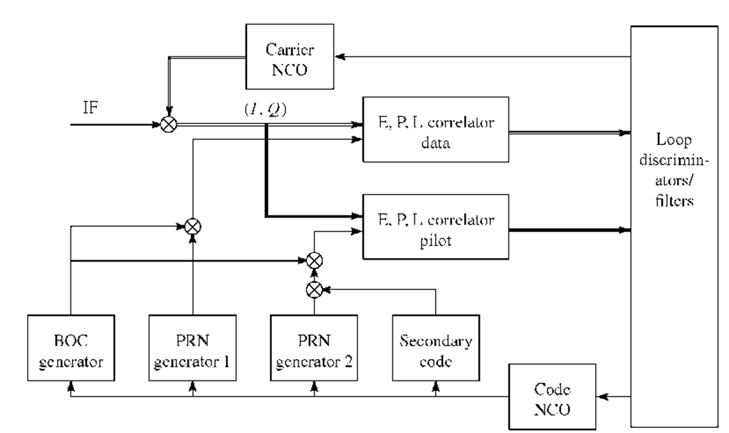
FIGURE B.7. Generic L1 OS tracking architecture.
The Galileo acquisition and tracking might need additional techniques to acquire/track the right peak of the ACF if the L1 OS signals will use the proposed CBCS coding scheme, confer Hein et al. (2005). Depending on the configuration of the CBCS coding scheme, ACFs with multiple, local extreme might occur.
A relatively simple false lock detection consisting of checking the ACF signal power in the vicinity of the tracked point could be implemented. This could be done with either extra correlator arms, situated "very early" and "very late" with respect to the early, prompt, and late arms, or it could be done by periodically jumping to neighboring code phases with the existing early, prompt, and late correlators.
Acquisition of Galileo Signals The acquisition of Galileo signals can be carried out as with GPS signals except from the differences mentioned in the previous subsection. In the case of the multiple peak correlation function, the local extremes could be ignored in the acquisition process due to the limited code phase resolution. The check for false locks should then be carried out when the handover from acquisition to tracking has taken place and the DLL has converged.
The dwell time dictates the maximum step for the frequency search. For the minimum length of 4 ms the maximum frequency step is 250 Hz (was 1 kHz for the 1 ms dwell time). For an improved performance a 125 Hz would be a better choice.
Tracking The high level architecture of the tracking block is almost exactly the same in the basic BOC(1,1) case as in GPS. The main differences are the new code generators (BOC, PRN, and secondary code) and longer minimum dwell times. A generic L1 OS tracking architecture is shown in Figure B.7.
The downconversion from IF to baseband is done with the usual carrier NCO and mixer. A separate PRN code generator (or look-up table depending on the final implementation) is used for the local data and pilot channel PRN code replicas. Both local codes are combined with the BOC subcar-rier. The pilot channel code is combined with the slow varying secondary code. All code generators are controlled by the strobe signal from the code NCO, although the secondary code generator uses a divided version of this timing signal. Suitable discriminators and loop filters provide the control signals for both NCOs as usual.
Both the data and pilot signals must be tracked together (combined tracking) to maximize receiver performance.
Data Demodulation and Decoding The demodulation will need an updated preamble search function. The code will have to employ a deinterleaver to put the received symbols (FEC encoded bits) in the right order. The MATLAB communication toolbox has built-in functions for interleaving and deinter-leaving.
A Viterbi decoder must be used to decode the symbol stream encoded by the FEC algorithm. The MATLAB communication toolbox has a built-in function vitdec to decode the FEC stream. The subframes have 6 tail bits set to zero to "initialize" the Viterbi decoder at the start of the next subframe. Therefore, the decoding can commence at the start of any subframe without prior knowledge of the navigation data stream.
The CRC check must be computed to detect any errors. The algorithm is very similar but not identical with that of GPS.
The actual locations of all transmitted data parameters in the data messages will be different. Also, some data will be transmitted in the Galileo system that is not transmitted in GPS. Therefore, new code must be written to decode navigation messages.
Decoding of ephemerides and almanac data is very similar to that of GPS once the data fields are read from the data messages. Decoding of time-related fields will need minor changes due to new width of the data fields and scale factors.
Position Computation The position computation is exactly the same as in GPS once the time-related data and ephemerides are decoded. There is a small difference in the coordinate systems (few centimeters) between GPS and Galileo. Care must be taken to handle this properly in case of very precise measurements.


