The Galileo system offers several services, a few are free of charge and the rest are commercial. In this topic we deal only with the L1 OS signal (OS for open service).
The L1 OS signal alone is expected to guarantee a horizontal accuracy better than 15 m, a vertical accuracy better than 35 m, a velocity accuracy better than 50 cm/s, and a timing accuracy better than 100 ns.
The augmentation from a single-frequency to a dual-frequency Galileo receiver naturally includes the E5a signal. For a dual frequency receiver the corresponding accuracies are 7 m, 15 m, 20 cm/s, and 100 ns.
All Galileo satellites use the same frequency bands and make use of code division multiple access (CDMA) technique. Spread spectrum signals will be transmitted including different ranging codes per signal, per frequency, and per satellite. All signals are transmitted in a right-hand circular polarization.
In this topic we rely on Anonymous (2005). For more details the reader is referred to this document; also note that all information is to be considered preliminary.
Signal Theoretical Considerations
Today when designing the Galileo signals the situation is very different from the days when the GPS signals were designed. Nowadays applications with difficult signal reception set the specifications for GNSS; the receiver may be used in the woods or indoors. This puts the most demanding efforts on the signal design.
Additionally, the wealth of digital signal processing experience over that time means many hands to the pump. The following considerations are based on Mattos (2004).
The L1 OS signal is transmitted on the frequency![]() The signal is composed of three channels, called A, B, and C. L1-A is identical to L1 PRS (PRS for public regulated service), which is a restricted access signal. Its ranging codes and navigation data are encrypted. The data signal is L1-B (meaning the B channel within L1) and the data-free signal is L1-C (meaning the C channel within L1). A data-free signal is also called a pilot signal. It is made of a ranging code only, not modulated by a navigation data stream.
The signal is composed of three channels, called A, B, and C. L1-A is identical to L1 PRS (PRS for public regulated service), which is a restricted access signal. Its ranging codes and navigation data are encrypted. The data signal is L1-B (meaning the B channel within L1) and the data-free signal is L1-C (meaning the C channel within L1). A data-free signal is also called a pilot signal. It is made of a ranging code only, not modulated by a navigation data stream.
The L1 OS signal has a 4092 code length with a 1.023 MHz chipping rate giving it a repetition rate of 4 ms; on the pilot signal a secondary code of length 25 chips extends the repetition interval to 100 ms.
Under some circumstances it may be difficult to separate the wanted signal from the unwanted ones and the unwanted one is often a cross correlation from another satellite as the inherent CDMA isolation of the codes is only around 21 dB. The cross-correlation problem is solved by using very long codes. However, longer codes also delay the acquisition process. In most cases the processor must search at half-chip offsets; thus, 8184 possibilities for the L1 OS code. To search the very long code lengths proposed for the new signals would be impractical, so the codes have been designed with escape routes. The most common one is called a tiered code. This means it is built in layers so that when you have a strong signal you can acquire on a simple layer, with less time-domain possibilities, only switching to the full-length code when required.
The minimum bandwidth is generally twice the chipping rate for simple codes, while for BOC codes it is twice the sum of chipping rate and offset code rate. Thus, the minimum practical bandwidth for the Galileo L1 OS is 8 MHz. For precise tracking of the code a bandwidth wider than the minimum is generally used.
Within this 4 ms period the signal-to-noise ratio (SNR) prevents the downloading of data for signals weaker than 25dB/Hz. The data-download situation is improved by using forward error correction codes (FEC), and block interleave also covers for burst errors. FEC convolutional codes spread the information from one user data bit over many transmitted symbols. If some of these are lost, the data bit can be recovered from the others. However, a burst error may destroy all the relevant symbols. Interleaving, which transmits the symbols in a scrambled sequence, means that a single burst error cannot destroy all the symbols relevant to a single user data bit. The downside is that it adds latency to the message, to allow for the interleaving/de-interleaving process. However, on the Galileo signal with 1 s packets this is not a problem.
The 4 ms repetition rate is ideal because there is one symbol per code epoch. When the code is synchronized, we know that we will not hit a data bit edge because these always occur at the start of a code sequence.
The signal is the product of carrier, spreading code, BOC, and data. Traditionally, the RF hardware removes the carrier, the correlators remove the BOC(1,1)![]() code, leaving the data and the residual Doppler to be removed/measured by a processor. With the BOC(1,1) codes, the BOC component should have been considered part of the spreading code for tracking and positioning; but it is equally viable to consider it part of the carrier during the acquisition phase, and remove it prior to the empirical correlation of acquisition.
code, leaving the data and the residual Doppler to be removed/measured by a processor. With the BOC(1,1) codes, the BOC component should have been considered part of the spreading code for tracking and positioning; but it is equally viable to consider it part of the carrier during the acquisition phase, and remove it prior to the empirical correlation of acquisition.
The ACF of a BOC(1,1) code has three peaks, not just one, so care must be taken to ensure that the correct one has been found.
Galileo L1 OS Signal
In the following we describe and combine all elements necessary to generate the Galileo L1 OS signal.
The transmitted bandwidth is 40 x 1.023 MHz = 40.92 MHz. The minimum received power for the L1 OS signal is -157dBW for elevation angles between 10° and 90°. The chip length of the ranging code is
The actual chips for the individual satellites are likely to be generated as a truncated Gold code. Higher chipping rates provide better accuracy. Longer codes reduce cross correlation to more acceptable levels, although acquisition time is longer.
The corresponding ranging code rates are
and subcarrier rates
Channel C uses both a primary and a secondary code of length![]() chips and
chips and![]() chips, respectively. The primary code is a truncated Gold sequence,so when the number of 4092 chips is reached, the register is reset to its initial state. We remember a Gold sequence is obtained as modulo-2 addition of the output from two shift registers. The initial state for the first register consists of mere ones while the second register depends on the specific subcarrier and satellite.
chips, respectively. The primary code is a truncated Gold sequence,so when the number of 4092 chips is reached, the register is reset to its initial state. We remember a Gold sequence is obtained as modulo-2 addition of the output from two shift registers. The initial state for the first register consists of mere ones while the second register depends on the specific subcarrier and satellite.
The secondary code modulates 25 specific repetitions of the primary code. For each subcarrier all satellites transmit the same secondary code: the octal sequence 34,012,662. The resulting code length is 4092 x 25. In Galileo lingo the final code is called a tiered code.
Let the primary code generator work with chip rate![]() The secondary code generator has chip rate
The secondary code generator has chip rate![]() where
where![]() is the length in chips of the primary code. In all signal modulations the logical levels 1 and 0 are defined as signal levels -1 and 1 (polar non-return-to-zero representation).
is the length in chips of the primary code. In all signal modulations the logical levels 1 and 0 are defined as signal levels -1 and 1 (polar non-return-to-zero representation).
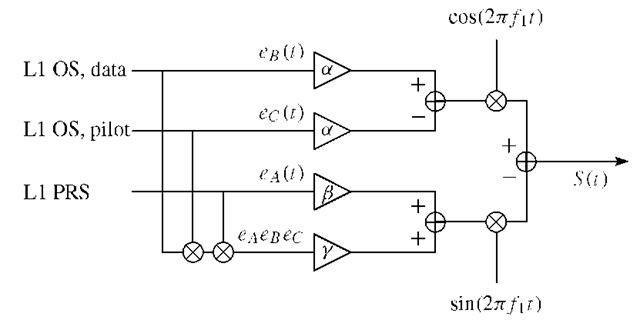
FIGURE 3.1. Galileo modulation scheme. The scheme is based on the modulation principle coherent adaptive subcarrier modulation (CASM).
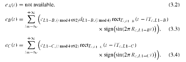
Now we have information for defining the binary signal components for channels B and C. However, information on channel A is not available. Based on this information and the modulation scheme depicted in Figure 3.1, we will describe the Galileo signal L1 OS.
The signal component for channel B results from the modulo-2 addition of the navigation data stream![]() the PRN code sequence
the PRN code sequence![]() and the B subcarrier
and the B subcarrier![]() The final component is called eB. Likewise, the C channel results from the modulo-2 addition of the C channel PRN code sequence
The final component is called eB. Likewise, the C channel results from the modulo-2 addition of the C channel PRN code sequence![]() with the C channel subcarrier
with the C channel subcarrier![]() The component is
The component is![]() The binary signal components are as follows:
The binary signal components are as follows:
Signal Generation
Signal expressions are given for the power normalized complex envelope (i.e., baseband version) s(t) of a modulated bandpass signal S(t). Both are described in terms of its in-phase I and quadrature Q components by the following generic expressions:
and normalized baseband signal
Coherent Adaptive Subcarrier Modulation
The three channel signals![]() of the L1 OS signal are multiplexed using coherent adaptive subcarrier modulation (CASM), (see Figure 3.1), which is a multichannel modulation scheme also known as tricode hexaphase modulation (or interplex modulation).
of the L1 OS signal are multiplexed using coherent adaptive subcarrier modulation (CASM), (see Figure 3.1), which is a multichannel modulation scheme also known as tricode hexaphase modulation (or interplex modulation).
CASM is used to ensure that the signal transmitted from the satellite has a constant power envelope, i.e., the total transmitted power does not vary over time. Thus, the transmitted information is not contained in the signal amplitude and the transmitted signal amplitude becomes less critical. This is a very desirable property of the signal since it allows the use of efficient "class C"-like power amplifiers.
The L1 OS data and pilot signals are modulated onto the carrier in-phase component while the L1 PRS signal is modulated onto the quadrature component. The combined signal is![]()
In this expression![]() are amplification factors that determine the distribution of useful power among the channels A, B, and C. We assume B and C have equal power.
are amplification factors that determine the distribution of useful power among the channels A, B, and C. We assume B and C have equal power.
For given relative signal powers we want to solve for these variables. So let us assume a relative signal power of 50% for A, and 25% for both B and C.
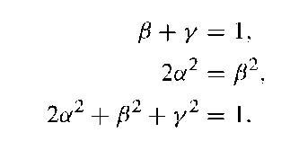
The first condition expresses that the norm of the I and the Q part of the signal S must be unity:
The condition of equal power for both I and Q channels leads to
Finally, the condition that the combined power equals one leads to
In total, we have three equations in three unknowns:
TABLE 3.1. Combination of three binary signals in CASM
|
L1 PRS |
L1 OS D |
L1 OS P |
 |
 |
 |
|
1 |
1 |
1 |
0 |
1 |
1 |
|
1 |
1 |
-1 |
0.9428 |
0.3333 |
1 |
|
1 |
-1 |
1 |
-0.9428 |
0.3333 |
1 |
|
1 |
-1 |
-1 |
0 |
1 |
1 |
|
-1 |
1 |
1 |
0 |
-1 |
1 |
|
-1 |
1 |
-1 |
0.9428 |
-0.3333 |
1 |
|
-1 |
-1 |
1 |
-0.9428 |
-0.3333 |
1 |
|
-1 |
-1 |
0 |
-1 |
1 |
The useful solution is
The given choice of relative signal powers defines the following signal:
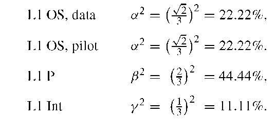
The product![]() is the intermodulation product L1 Int in CASM,which ensures the constant envelope property of the transmitted signal. The transmitted power is distributed as follows:
is the intermodulation product L1 Int in CASM,which ensures the constant envelope property of the transmitted signal. The transmitted power is distributed as follows:
This means that only 88.88% of the total transmitted power is useful. The power offered for the L1 Int signal is wasted; apparently this waste is the price we must pay to obtain a constant envelope for the signal S(t).
The L1 modulation scheme is specifically designed to allow independent processing of the L1 OS signal and the L1 PRS signal in the Galileo receiver. Only the quadrature component needs to be considered when the PRS signal is received. The in-phase part does not contain information about the PRS signal, as seen in Figure 3.1. Since the intermodulation product transmitted on the quadrature component does not carry any information, only the in-phase component is useful for reception of the L1 OS signals.
FIGURE 3.2. IQ plot of CASM output.
Table 3.1 shows the eight possible signal combinations of the three binary signals![]() Also shown are the real and imaginary parts of S(t) (corresponding to the in-phase and quadrature signal components) as well as the norm of the IQ vector.
Also shown are the real and imaginary parts of S(t) (corresponding to the in-phase and quadrature signal components) as well as the norm of the IQ vector.
It is observed that the length of the IQ vector of S(t) is always 1. This is also seen from the IQ plot in Figure 3.2 where the unit circle is included for reference.
From Table 3.1 it also appears that the three binary signals are combined to a representation with six possible phases, thus the name tricode hexaphase. It is seen from the table that the transmitted PRS code is equal to the sign of the quadrature component. It is also seen that the in-phase component can only assume three different values, so unambiguous mapping from received in-phase signal to transmitted signal is not possible. The table shows that the data channel is equal to the sign of the in-phase component when the data and pilot channels are not equal, and that the in-phase component is zero when the data channel is equal to the pilot channel. This means that all the transmitted power is concentrated in the quadrature channel whenever the data and pilot signals are equal.


