Multipath
Of the multiple error sources associated with GNSS signal processing, multipath directly impacts the code tracking performance. With the prior description of how code tracking is implemented, it makes sense to investigate how multipath impacts the code tracking loop.
The signal observed at the receiver is a distorted version of the one transmitted. One distortion effect is called multipath propagation or, for short, multipath.
If the receiver can directly see the satellite, a part of the received signal has propagated via the direct path from the satellite to the receiver. This signal component is delayed according to the distance between the satellite transmitter and the receiver. The signal component propagated via the direct path usually is by far the strongest part of the received signal.
In addition to the direct signal, the receiver may observe other signals propagating via other and longer paths. This can happen if the radio wave reaches the receiver after interaction with one or more objects/obstacles in the environment. Different kinds of interactions between radio waves and objects exist, but in the context of GNSS it suffices to think of an interaction as a reflection altering the direction of propagation, amplitude, polarity, and phase of the radio wave.
First we consider the simple case where the transmitted signal reaches the receiver via two paths. Thus, the received signal consists of two components: a direct component and a signal component reaching the receiver via a reflection on a nearby building. In this case the reflected signal component is a delayed, phase-shifted, and attenuated version of the line-of-sight signal component. Due to the change in phase and delay, the two signal components interfere. In case the reflected and the direct signals are in phase, the amplitude of the sum is larger than the amplitude of each of the components. This we call constructive interference; see Figure 7.16. On the other hand, if the direct and reflected signals are out of phase, the amplitude of the sum signal decreases and we talk about destructive interference. In case the relative phase between the direct and reflected signals rapidly changes the amplitude of the sum signal, we say that the received signal is fading. A signal component reaching the receiver via a different path than the direct path is called a multipath component.
In general, the received signal x (t) is composed of the direct signal and M – 1 multipath components. Let![]() denote the amplitude of the ith multipath component, let D denote the navigation message, let C denote the code, let
denote the amplitude of the ith multipath component, let D denote the navigation message, let C denote the code, let![]() denote the multipath error, let the frequency change be
denote the multipath error, let the frequency change be![]() the phase offset be
the phase offset be![]() and, finally, add a noise term n(t); then the signal can be described as
and, finally, add a noise term n(t); then the signal can be described as
To simplify the discussion we consider a two-path scenario (M = 2) and make the following assumptions:
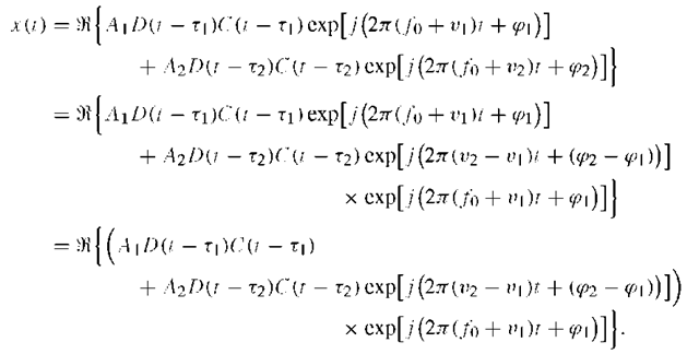
In other words we have assumed that the parameters (amplitudes, delays, and Doppler shifts) are constant over the time period we consider. In this case, x(t) can be reduced to
We now exploit
Defining the instantaneous phase difference between the two signal components
![]() the output of the integrators in the DLL can be approximated as
the output of the integrators in the DLL can be approximated as
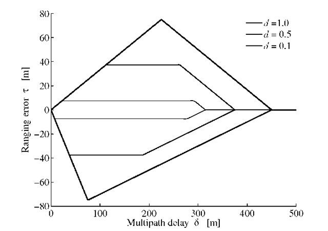
FIGURE 7.17. Multipath error envelope for noncoherent early/late detector for C/A code, ![]() The positive multipath error corresponds to constructive interference while negative multipath error corresponds to destructive interference.
The positive multipath error corresponds to constructive interference while negative multipath error corresponds to destructive interference.
The output of the envelope discriminator is
As mentioned before, the amplitude of the sum signal depends on the relative phase![]() between the direct and the reflected signal components. We consider the two special cases of constructive and destructive interference:
between the direct and the reflected signal components. We consider the two special cases of constructive and destructive interference:
Constructive interference. In this case![]() and
and![]()
![]()
![]()
Destructive interference Here,
If the receiver is moving, it is very likely that![]() and the relative phase changes over time. Therefore, the envelope of the received signal will fluctuate over time as the two signal components interfere.
and the relative phase changes over time. Therefore, the envelope of the received signal will fluctuate over time as the two signal components interfere.
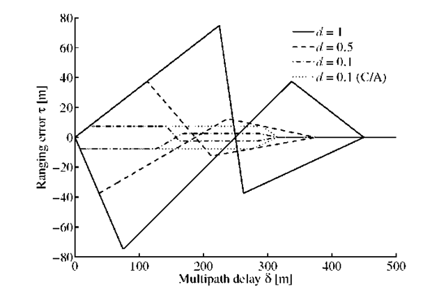
FIGURE 7.18. Multipath error envelope for noncoherent early/late detector for BOC(1,1). Negative ranging error corresponds to destructive interference.
As a measure of the magnitude of the fluctuations we define the relative amplitude as
In practice, the amplitude of the direct component is larger than the reflected component and thus![]() is somewhat less than one.
is somewhat less than one.
Equation (7.29) is graphed as the upper half of Figure 7.17 for![]() and for three values of the correlator spacing d = 0.1, 0.5, and 1.0. The upper part of the figure corresponds to constructive interference while the lower part corresponds to destructive interference; see Equation (7.30). All actual multipath errors lie within the combined envelope!
and for three values of the correlator spacing d = 0.1, 0.5, and 1.0. The upper part of the figure corresponds to constructive interference while the lower part corresponds to destructive interference; see Equation (7.30). All actual multipath errors lie within the combined envelope!
In Figure 7.17 the initial slope is a function of multipath amplitude and delay![]() only It is independent of correlator and PRN chipping rate
only It is independent of correlator and PRN chipping rate![]() We all the C/A-code pseudorange multipath error can approach 147 m, theoretically. However, errors of 10 m or less are far more common. Large errors can be encountered in urban environments.
We all the C/A-code pseudorange multipath error can approach 147 m, theoretically. However, errors of 10 m or less are far more common. Large errors can be encountered in urban environments.
Our investigation assumes infinite GPS signal bandwidth. Bandwidths of 1020 MHz yield results that are similar to those for the infinite bandwidth case. For short-delay multipath (small![]() )the finite bandwidth effects are much less significant.
)the finite bandwidth effects are much less significant.
In conclusion: Multipath propagation deforms the ideal correlation peak because the received signal is a sum of signal components. The multipath components arrive later at the receiver and contribute additional correlation peaks. Thus, the early-late correlator samples may not be centered on the true arrival time of the direct path.
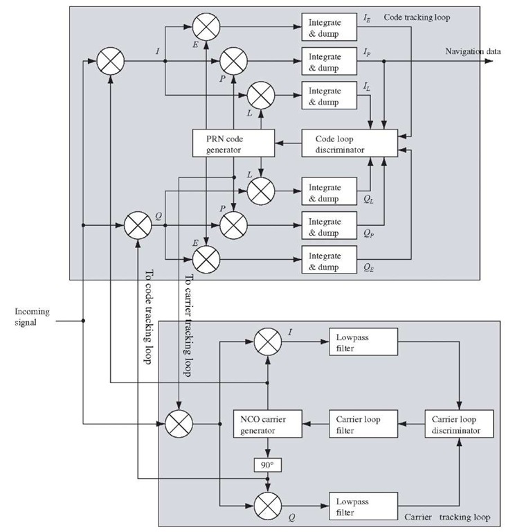
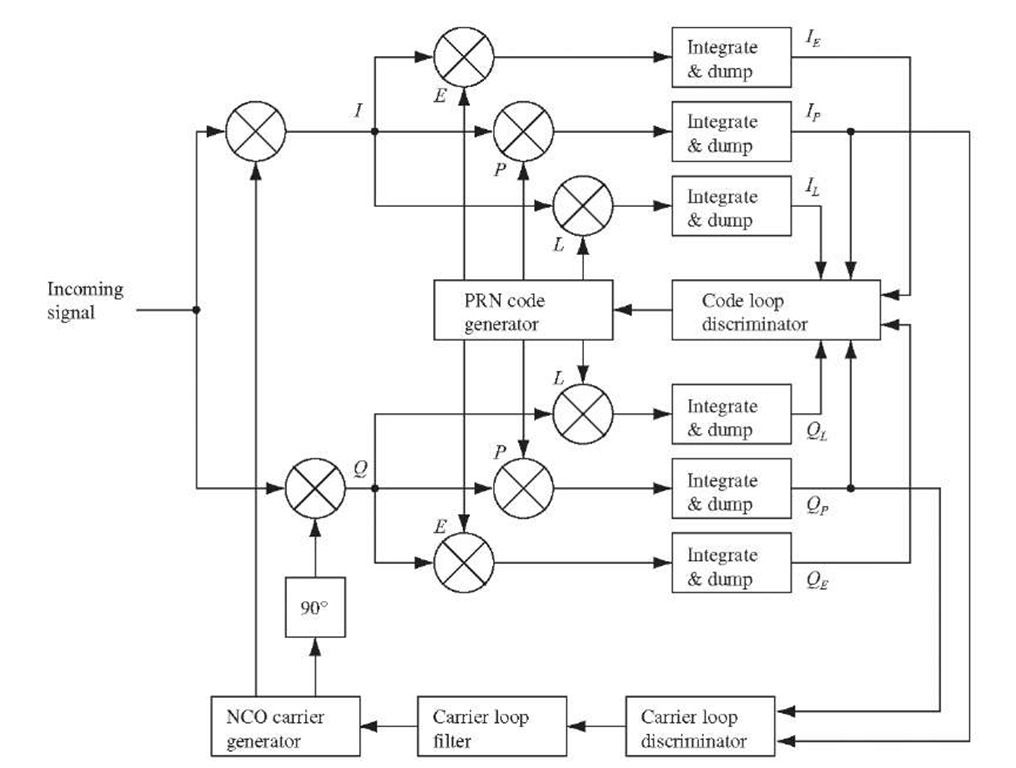
FIGURE 7.19. Block diagram of the combined DLL and PLL tracking loops.
We note that in MATLAB the ACF can be coded as
Next we determine the multipath error envelope for Galileo BOC(1,1). The result is plotted in Figure 7.18. Comparing Figures 7.17 and 7.18 for correlator spacing d = 0.1 we see that the C/A code multipath error envelop is sensitive for multipath signals with a relative path delay up to 300m. The resulting range errors![]() are between
are between![]() For BOC(1,1) the corresponding value is 150 m and range errors of
For BOC(1,1) the corresponding value is 150 m and range errors of![]() This demonstrates that BOC(1,1) signals are better to handle multipath signals than C/A code signals!
This demonstrates that BOC(1,1) signals are better to handle multipath signals than C/A code signals!
The multipath error envelopes are computed from equations like (7.29) and (7.30). Figures 7.17 and 7.18 are plotted by using the powerful ezplot command. With correlator spacing d = 0.1 and multipath delays 8 in the range 0-157 m
FIGURE 7.20. The block diagram of a complete tracking channel on the GPS receiver.
we obtain ranging errors![]() in the interval
in the interval![]() for
for![]() in the range 157-317 m the delay
in the range 157-317 m the delay![]() is within
is within![]() Obviously the delay range
Obviously the delay range![]() strongly depends on the correlator spacing d; some papers even mention d = 1 /25. See also Winkel (2005).
strongly depends on the correlator spacing d; some papers even mention d = 1 /25. See also Winkel (2005).
Complete Tracking Block
In the previous sections, the code tracking loop and the carrier tracking loop are described in detail. The following describes how the code tracking loop and the carrier tracking loop can be joined to minimize the computational load.
Figure 7.19 shows the code tracking loop and the carrier tracking loop combined. It can be seen from the figure that the PRN code replica used to wipe off the PRN code in the carrier tracking loop is coming from the code tracking loop. It can also be seen that the two local carrier replicas used to wipe off the carrier wave in the code tracking loop are coming from the carrier tracking loop. The block diagram in Figure 7.19 contains 11 multiplications. These multiplications are the most time-consuming operations on the block diagram.
Figure 7.20 shows an optimized version of the combined tracking loops. Here the I and Q inputs to the phase discriminator are the![]() correlatio from the code tracking loop. In this way the three multiplications in the Costas loop are eliminated, and hereby the computation time is reduced.
correlatio from the code tracking loop. In this way the three multiplications in the Costas loop are eliminated, and hereby the computation time is reduced.
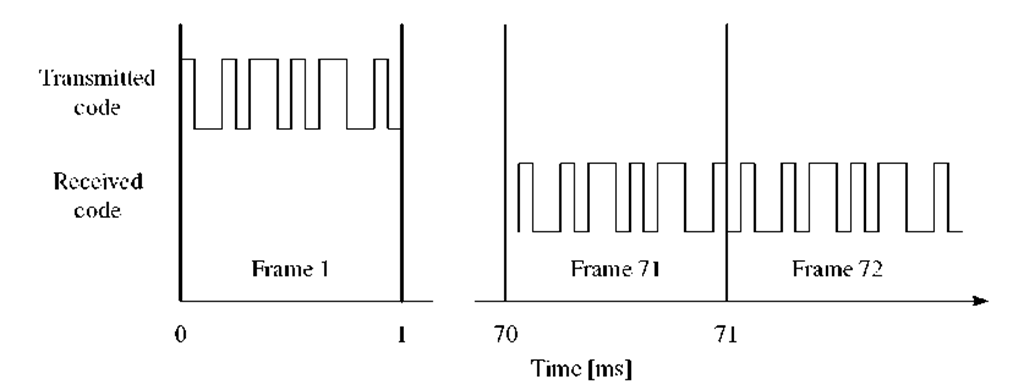
FIGURE 7.21. The delay between the time of transmission at the satellite and time of reception at the receiver.
Pseudorange Computations
Precise estimation of the pseudorange from a satellite to the receiver is crucial for a modern C/A code GPS receiver. The relationship between the standard deviation of the observations and that of the coordinates of the receiver position is
where![]() is the standard deviation of the receiver position, a0 is the standard deviation of unit weight. PDOP is the position dilution of precision, which depends on the geometry of the satellite constellation. Optimal accuracy of the position is obtained when the standard deviation of unit weight is as small as possible.
is the standard deviation of the receiver position, a0 is the standard deviation of unit weight. PDOP is the position dilution of precision, which depends on the geometry of the satellite constellation. Optimal accuracy of the position is obtained when the standard deviation of unit weight is as small as possible.
A pseudorange measurement is computed as the travel time from the satellite to the receiver multiplied by the speed of light in vacuum. The receiver has to estimate exactly when the start of a frame arrives at the receiver. This is done by adding the code phase to the time when the frame entered the receiver.
In Figure 7.21, the satellite transmits the start of the C/A code at t = 0 ms. This signal is received by the receiver approximately 70 ms after it is transmitted from the satellite. A range from the satellite to the receiver of 21,000 km corresponds to a travel time of 70 ms. As described before, the receiver is using block processing. That is, to calculate an accurate pseudorange and hereby an accurate position, the exact start of the C/A code in frame 71 in Figure 7.21 has to be found.
Figure 7.22 shows the first 700 samples of frame 71 in detail. The receiver has a time tag for the start of the frame. The problem is then to determine exactly where the start of the code is in the frame of data. In Figure 7.22, the start of the C/A code is at sample number 605, which is the correct code start in the simulated data used in this section.
Since the sampling frequency of the reference data set is at 38.192 MHz, each sample corresponds to
FIGURE 7.22. Close-up of frame 71 from Figure 7.21. In this case, the beginning of the C/A code is at sample 605 of the total of 38,192.
Since the prompt code is precisely aligned with the incoming signal to the nearest sample, the maximum error as a result of the discrete samples will be half that or < 5 m, which is sufficient for C/A code-type signals. If the sampling frequency is lower, a higher precision is required. Then it is possible to use the residual code phase at the end of each ms period to further refine that accuracy.


