Code Tracking
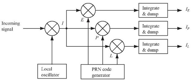
The goal for a code tracking loop is to keep track of the code phase of a specific code in the signal. The output of such a code tracking loop is a perfectly aligned replica of the code. The code tracking loop in the GPS receiver is a delay lock loop (DLL) called an early-late tracking loop. The idea behind the DLL is to correlate the input signal with three replicas of the code seen in Figure 7.10.
The first step in Figure 7.10 is converting the C/A code to baseband, by multiplying the incoming signal with a perfectly aligned local replica of the carrier wave. Afterwards the signal is multiplied with three code replicas. The three replicas are nominally generated with a spacing of![]() chip. After this second multiplication, the three outputs are integrated and dumped. The output of these integrations is a numerical value indicating how much the specific code replica correlates with the code in the incoming signal.
chip. After this second multiplication, the three outputs are integrated and dumped. The output of these integrations is a numerical value indicating how much the specific code replica correlates with the code in the incoming signal.
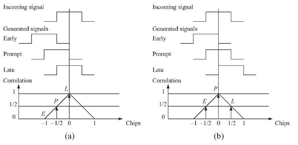
The three correlation outputs![]() are then compared to see which one provides the highest correlation. Figure 7.11 shows an example of code tracking. In Figure 7.11a the late code has the highest correlation, so the code phase must be decreased.
are then compared to see which one provides the highest correlation. Figure 7.11 shows an example of code tracking. In Figure 7.11a the late code has the highest correlation, so the code phase must be decreased.
FIGURE 7.10. Basic code tracking loop block diagram.
FIGURE 7.11. Code tracking. Three local codes are generated and correlated with the incoming signal. (a) The late replica has the highest correlation so the code phase must be decreased, i.e., the code sequence must be delayed. (b) The prompt code has the highest correlation, and the early and late have similar correlation. The loop is perfectly tuned in.
In Figure 7.11b the highest peak is located at the prompt replica, and the early and late replicas have equal correlation. In this case, the code phase is properly tracked.
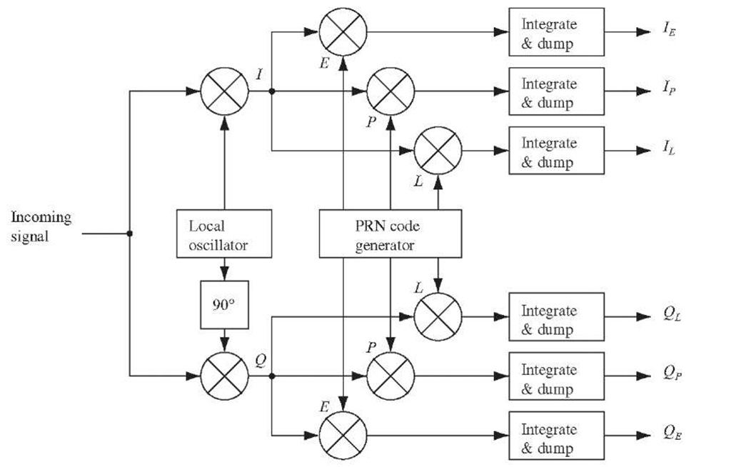
The DLL with three correlators as in Figure 7.10 is optimal when the local carrier wave is locked in phase and frequency. But when there is a phase error on the local carrier wave, the signal will be more noisy, making it more difficult for the DLL to keep lock on the code. So instead the DLL in a GPS receiver is often designed as in Figure 7.12.
FIGURE 7.12. DLL block diagram with six correlators.
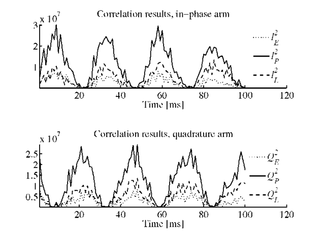
FIGURE 7.13. Output of the six correlators in the in-phase and quadrature arms of the tracking loop. Acquisition frequency offset is 20 Hz and PLL noise bandwidth is 15 Hz (for demonstration purpose).
The design in Figure 7.12 has the advantage that it is independent of the phase on the local carrier wave. If the local carrier wave is in phase with the input signal, all the energy will be in the in-phase arm. But if the local carrier phase drifts compared to the input signal, the energy will switch between the in-phase and the quadrature arm. For demonstration purposes, Figure 7.13 shows such a situation where the phase of the carrier replica drifts compared to the phase of the incoming signal. The upper plot shows the output of the three correlators in the in-phase arm, and the lower plot shows the correlation output in the quadrature arm of the DLL with six correlators. This situation is a result of different frequencies for the signal and the replica; it results in a constantly changing phase difference (misalignment). There are a few reasons why this can happen, for example, the PLL could be not in a lock state.
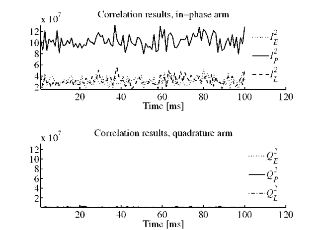
FIGURE 7.14. Output of the six correlators in the in-phase and quadrature arms of the tracking loop. The local carrier wave is in phase with the input signal.
TABLE 7.2. Various types of delay lock loop discriminators and a description of them
Figure 7.14 shows a case when the PLL is in a lock state. Because of the precise carrier replica from the PLL, it is seen in Figure 7.14 that the correlators are constant over time. This would not be the case if the carrier replica is not adjusted to match the frequency and phase of the incoming signal.
If the code tracking loop performance has to be independent of the performance of the phase lock loop, the tracking loop has to use both the in-phase and quadrature arms to track the code.
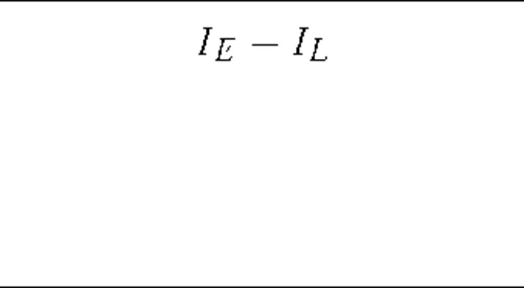
The DLL now needs a feedback to the PRN code generators if the code phase has to be adjusted. Some common DLL discriminators used for feedback are listed in Table 7.2.
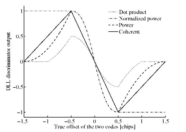
The table shows one coherent and three noncoherent discriminators. The requirements of a DLL discriminator is dependent on the type of application and the noise in the signal. The discriminator function responses are shown in Figure 7.15.
FIGURE 7.15. Comparison between the common DLL discriminator responses.
Figure 7.15 shows the coherent discriminator and three noncoherent discriminators using a standard correlator. The figure is produced from ideal ACFs, and the space between the early, prompt, and late is![]() chip. The space between the early, prompt, and late codes determines the noise bandwidth in the delay lock loop. If the discriminator spacing is larger than
chip. The space between the early, prompt, and late codes determines the noise bandwidth in the delay lock loop. If the discriminator spacing is larger than![]() chip, the DLL would be able to handle wider dynamics and be more noise robust; on the other hand, a DLL with a smaller spacing would be more precise. In a modern GPS receiver the discriminator spacing can be adjusted while the receiver is tracking the signal. The advantage from this is that if the signal-to-noise ratio suddenly decreases, the receiver uses a wider spacing in the correlators to be able to handle a more noisy signal, and hereby a possible code lock loss could be avoided.
chip, the DLL would be able to handle wider dynamics and be more noise robust; on the other hand, a DLL with a smaller spacing would be more precise. In a modern GPS receiver the discriminator spacing can be adjusted while the receiver is tracking the signal. The advantage from this is that if the signal-to-noise ratio suddenly decreases, the receiver uses a wider spacing in the correlators to be able to handle a more noisy signal, and hereby a possible code lock loss could be avoided.
The implemented tracking loop discriminator is the normalized early minus late power. This discriminator is described as
where![]() are output from four of the six correlators shown in Figure 7.13. The normalized early minus late power discriminator is chosen because it is independent of the performance of the PLL as it uses both the in-phase and quadrature arms. The normalization of the discriminator causes that the discriminator can be used with signals with different signal-to-noise ratios and different signal strengths.
are output from four of the six correlators shown in Figure 7.13. The normalized early minus late power discriminator is chosen because it is independent of the performance of the PLL as it uses both the in-phase and quadrature arms. The normalization of the discriminator causes that the discriminator can be used with signals with different signal-to-noise ratios and different signal strengths.
The tracking loop generates three local code replicas. In this section, the chip space between the early and prompt replicas is half a chip.
As was described, the DLL can be modeled as a linear PLL and thus the performance of the loop can be predicted based on this model. In other words the loop filter design is the same, just the parameter values are different.
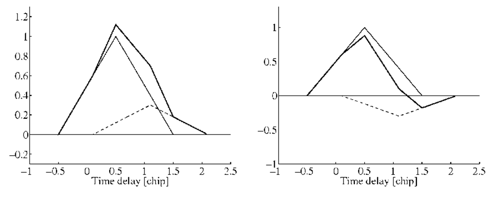
FIGURE 7.16. Constructive and destructive multipath interference. The solid thin line represents the original triangular correlation function; the dashed line the multipath correlation function, and the third line is the sum of the two.
![tmp2D-938_thumb[1] tmp2D-938_thumb[1]](http://what-when-how.com/wp-content/uploads/2012/02/tmp2D938_thumb1_thumb.png)
![tmp2D-940_thumb[1] tmp2D-940_thumb[1]](http://what-when-how.com/wp-content/uploads/2012/02/tmp2D940_thumb1_thumb.png)
![tmp2D-942_thumb[1] tmp2D-942_thumb[1]](http://what-when-how.com/wp-content/uploads/2012/02/tmp2D942_thumb1_thumb.png)
