Geoscience Reference
In-Depth Information
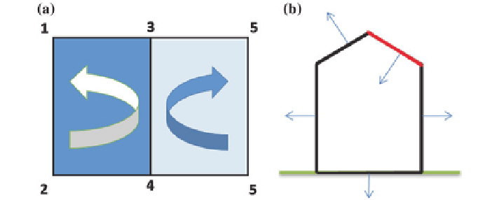
Fig. 11
Healing CS_FACEORIENT error
CS_OVERUSEDEDGE
: Any edge of the solid bounding more than two
polygons causes a topological error. In Fig.
10
if the self-intersection error is
healed then there will be an edge sharing 4 polygons. This type of error are not
possible to heal automatically the possible options are to manually edit the solid or
delete the polygons.
CS_FACEORIENT
: Each edge must bound two polygon and the orientation
of the edge must be opposite in the polygons. In Fig.
11
a two polygons P{P
1
,
P
2
, P
4
, P
3
, P
1
} anti-clockwise oriented and Q{P
6
, P
4
, P
3
, P
5
, P
6
} clockwise ori-
ented, are bound by the edge (P
4
, P
3
). But the order should be in one polygon
(P
4
, P
3
) and in another polygon (P
3
, P
4
). If all or most of the edges of a polygon
have wrong orientation then it is wrong oriented and healing would be to reverse
the order of the pointlist. So if pointlist Q is wrong oriented then the healing pro-
cess will correct the pointlist in {P
6
, P
5
, P
3
, P
4
, P
6
} and the orientation will be
anti-clockwise.
CS_FACEOUT
: If every polygon of a solid is wrong oriented then the solid
will be valid by face orientation check because each edge will find an opposite
pair. So every surface normal of a solid must direct outwards. Even after healing
the face orientation error it is not guaranteed that all the polygons will face out-
ward. In Fig.
11
b the red polygon has a face out error. Healing of this error is to
reverse the orientation of the polygon.
CS_CONCOMP
: If a solid contains a disconnected polygon then it has an
error and it will be detected by the outer edge check. But if the polygons defined
in a solid forms two valid solid like Fig.
12
then it will pass all the checks until
connected component check. Healing of this error is to convert each disconnected
solid into a solid data structure and delete the original solid.
CS_UMBRELLA
: Healing this error is still in progress but one option is to
split the adjacent polygons into groups where they are connected by edges and
then create new vertices for each group with same coordinates then move those
vertices a little bit away from each other like Fig.
13
.