Geoscience Reference
In-Depth Information
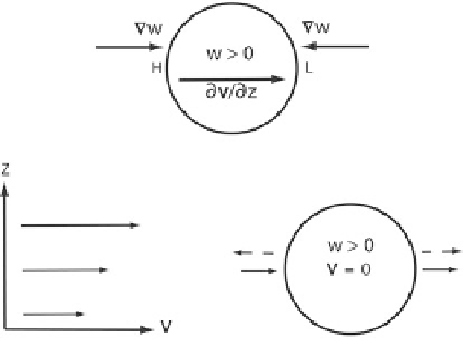
Figure 4.34. Illustration of how the dynamic perturbation pressure is high upshear and low
downshear from an updraft in a unidirectionally vertically sheared environment. (Top) Mathe-
matic description: the updraft gradient points in the same direction as the vertical shear vector
on the upshear side and in the opposite direction on the downshear side (cf. (4.46)). Thus, the
forcing function is negative on the upshear and positive on the downshear side, so that the
perturbation pressure is positive on the upshear side and negative on the downshear side.
(Bottom) Physical explanation: vertical variation of the wind vector is shown on the left. On the
right, it is seen that if the updraft moves along with the mean wind (middle wind vector on the
left), then at the top level air approaches the updraft from the west, decelerates to zero (because
the momentum characteristic of the wind in the layer below, which is the same as the vertically
averaged momentum, has been advected upward), and then accelerates to the east. This wind
field is consistent with the pressure gradient forces shown by the dashed vectors.
counter-rotating vortices that are strongest at mid-levels (
Figure 4.29,
top and
middle panels); in the Northern Hemisphere, the cyclonic (anticyclonic) member is
found to the right (left) of the updraft, with respect to the orientation of the
vertical shear vector. Perturbation low-pressure areas are associated at mid-levels
with each of the vortices (nonlinear, spin). Since vortices are strongest at mid-
levels and the perturbation pressure deficit is proportional to the square of the
perturbation (storm-related) vorticity (4.48), upward-directed perturbation
pressure forces are found at lower levels, below the altitude of the strongest
vorticity. Thus, new updrafts may be triggered in the off-shear (normal to the
shear) direction with respect to the original updraft.
In the absence of any precipitation, the updraft splits into two parts; each new
updraft then acts on environmental shear to produce two new updrafts on each
flank of the split updrafts (
Figure 4.35
); the process continues so that the two
outer updrafts propagate to the right and left of the shear vector, respectively.
The inner updrafts are likely to be situated in a region where precipitation falls,
where there is evaporative cooling, and consequently the original updraft decays;
in the absence of precipitation, these inner updrafts will propagate towards each
other. The net result is that updrafts following the original updraft split and pro-
pagate apart. Such behavior is observed in radar imagery and in numerical
simulations (
Figures 4.36
and
4.37
) and in the 1960s, when splitting storms were
Search WWH ::

Custom Search