Geoscience Reference
In-Depth Information
120
PLANE FAILURE
Slope angle, S
>
Discontinuity angle, D
>
Friction angle
Circular
failure
Toppling
failure
S
D
100
Dry slopes
I
WEDGE FAILURE
Discontinuity intersect, I
>
Slope angle, S
>
Friction angle
80
S
60
b
Wedge
failure
TOPPLING FAILURE
Tangent of slope angle, S
>
breadth/height of blocks,
b
h
h
40
Saturated slopes
20
Plane failure
CIRCULAR FAILURE
Restricted to non-
cohesive material and
intensely fractured
rock mass
0
0 0 0 0 0
Discontinuity angle, °degrees
50
60
70
80
90
determined by fracture geometry and condition. Note the
major reduction caused by saturated intermediate to high-
angled discontinuities.
Source: After Hoek and Bray (1977)
discontinuity, geometry and friction strength.
Failure modes on rock slopes
Sliding and toppling failures dominate rock slopes, taking
one or more of four forms determined by relations
between discontinuity geometry and slope (
Figure 13.17
).
Failure rarely needs to shear intact rock and might find
this more difficult (
Plate 13.17
).
The sole requirement for
sliding in discontinuous rock mass is one fracture surface
(
D
) steeper than the friction angle (
F
) but at a lower angle
than the rock wall slope (
S
), which allows it to appear,
or
daylight
, in the rock wall. Single fractures provide
where the release surface is the intersecting plane (
I
)
between two fractures.
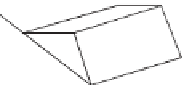
Toppling failure
occurs where a
primary fracture surface dips into the rock wall and
appears stable but is intersected by more widely spaced
fractures. Columnar blocks, defined by height (
h
) and
breadth (
b
), topple when their centre of gravity overhangs
a pivot. Fracture geometry, failure modes and rock wall
height relationships are shown in
Figure 13.18
.
Circular sliding is uncommon in hard rock, where
the 'massive' nature of orthogonal fracture sets provides
sufficient release surfaces, but may occur in densely frac-
tured material, soft sediments or when hard rock overlies
Plate 13.17
Quarry surfaces during blasting, showing
structural control on the release of blast energy and the
surviving rock wall. The tectonic fracture geometry deter-
Photo: Ken Addison
less resistant strata. In the former, initially steep slides are
released along less steep fractures as they approach the
rock wall foot, leaving circular scars. In the latter, the
incompetent
stratum (e.g. clays, shales) slumps, and may