Geoscience Reference
In-Depth Information
Interpolation
occurs within
the receiver
gather
Shot
position
along
the line
Traces with
a Common
Midpoint
Receiver position along the line
Fig. 2.25
Stacking diagram to illustrate shot record interpolation. The grey receivers mark the
position of the original recorded data. The data are sorted into receiver gathers in which the trace
spacing is half what it is in CMP gathers. Interpolation is used to create the additional traces shown
in red. Once sorted into CMP gathers the number of traces within each gather has doubled and the
trace separation has halved.
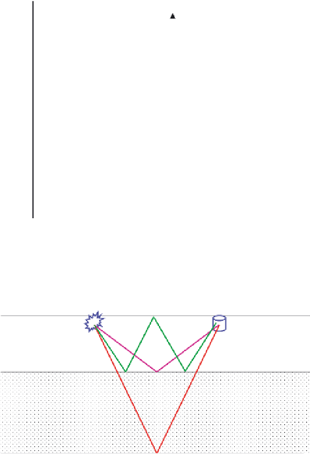
Fig. 2.26
Primary and multiple reflections. The red and purple events are primaries; they have a
single reflection along the ray-path. The green event has multiple reflections and in this case is the
first-order multiple of the purple event. The timing of the green event may be similar to underlying
primaries, and if it is not removed it may obscure the deeper reflectivity.
The next step in
fig. 2.21
is the process to remove multiples from the data.
Figure 2.26
explains the differences between primary events and multiples. Here again there are
a large number of choices of technique. Methods are based either on velocity move-
out differences, or on prediction based on the timing and geometry of the cause of