Geoscience Reference
In-Depth Information
0.2
0.1
0
Recorded reflection
Earth reflectiv
ity
0
50
100
150
200
−
0.1
−
0.2
−
0.3
−
0.4
TWT (ms)
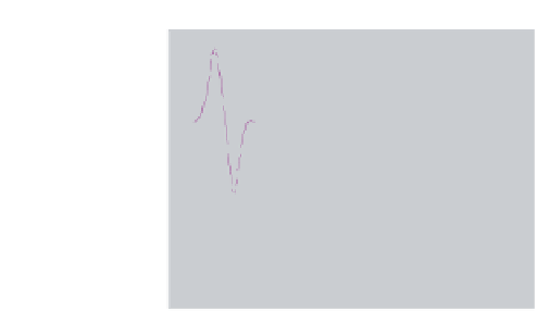
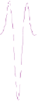
Fig. A2.1
Earth reflectivity, in red, shows that there are three reflectors. The trace in purple shows
what would actually be recorded; each reflector sends back a signal representing the wavelet, scaled
in amplitude by the reflection strength, and the final output is the sum of these three signal trains. It
is hard to visualise the earth reflectivity from the recorded trace when the reflectors are closely
spaced. Deconvolution tries to remove this confusion.
Depth migration
An implementation of migration that allows for ray-bending at interfaces where the seismic velocity
changes. The simplest type of migration (time migration) can cope with mild lateral changes in velocity
by changing the migration velocity (and therefore the curvature of the hyperboloid along which data
are summed in the Kirchhoff method). Where there are rapid lateral changes, such as in the presence
of steeply dipping interfaces across which there are large velocity changes, then the surface along
which data ought to be summed will no longer be a hyperboloid and has to be calculated in detail
by tracing the propagation of rays through a subsurface model. This is substantially more demanding
in computation time. It is also more difficult to build the correct subsurface velocity model, because
changes in velocity at any one level will affect rays traversing that level in ways that may be hard to
visualise without detailed computation.
DHI
A Direct Hydrocarbon Indicator is any feature on seismic data that gives evidence for the presence of
hydrocarbons, and is particularly useful in reducing the risk associated with drilling an exploration
well. Typical examples are an amplitude anomaly on the top-reservoir reflector that shows confor-
mance to structure, or a
flat spot
, a horizontal reflector due to a gas-oil or oil-water contact that cuts
across bedding-plane reflectors.
Dip moveout (DMO) correction
In the simplest approach to stacking, traces with the same source-receiver midpoint are added together
after correction for NMO. The output stacked trace is then treated as being a lower-noise version of the
trace that would be recorded if the source and receiver were coincident at the midpoint location used to
select the input traces. For reflection from a dipping interface in the subsurface, the reflection point is
not vertically below the source-receiver midpoint. It is displaced updip, by an amount which increases
as the source-receiver distance increases. Stacking traces with the same midpoint therefore adds
together traces that have been reflected from different points in the subsurface, inevitably smearing
the image. DMO processing corrects for this effect. It carries out a partial migration of the data, moving
energy for a reflecting point from the location seen on an actual finite-offset trace to the location that