Geoscience Reference
In-Depth Information
RUN 2
(B)
(A)
RUN 7
separation
zone I
separation
zone I
separation
zone II
separation
zone II
(C)
RUN 2
(D)
RUN 7
inner bank
outer bank
inner bank
outer bank
ve
×
3
25 m
ve
×
3
25 m
1025
1258
1025
1124
flow density (kg/m
3
)
flow density (kg/m
3
)
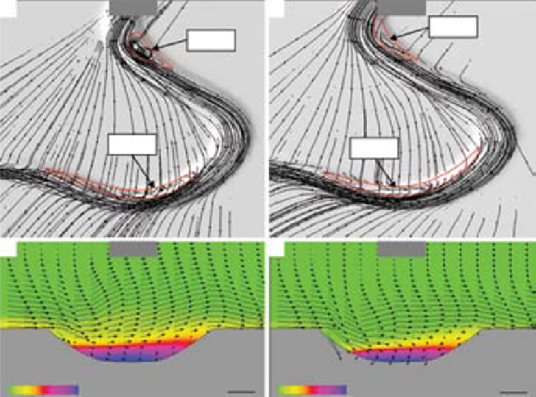
Fig. 14.
(A, B) Stream traces illustrating the vector field flow in Run 2 and Run 7. The separation zones are recognised as
areas of increased turbulence and chaotic flow. A) In Run 2, separation zones develop downstream of bend apexes and are
further intensified by the overriding overbank flow. B) In Run 7, separation zones develop further upstream than in Run 2 and
are less intense, possibly due to the less powerful overbank flow. (C) Density profile with 3D velocity vectors at the apex of
Bend 2 (Run 2). The profile shows there is a weak inwardly-oriented secondary flow cell at the base of the channel, hinting at
a cell reversal at higher flow velocities. The upper part of the channelised flow is characterised by an outwardly motion and
flow overspill at the outer bend. The high-density core does not seem to experience super elevation and is confined to the
centre of the channel. (D) Density profile with 3D velocity vectors at the apex of Bend 2 (Run 7). The secondary circulation cell
is better developed than in C, showing a basal-inward orientation. Overspill is less pronounced and as in C, the high-
density core is confined to the centre of the channel.
suspension fall-out deposition occurring in the
downstream part of inner bend (Fig. 13C; 14A).
These flows are therefore expected to be responsi-
ble for the downstream translation of submarine
channels where the upstream part of the point bar
is dominated by erosion and the downstream part
by deposition (also see Amos
et al
., 2010). If the
current is in disequilibrium with the channel
shape, such as the high-velocity currents in
our simulations, significant overspill will occur
at channel bends leading to substantial loss of
velocity and concentration of the remaining
channelised flow. These flows are thus inefficient
in maintaining constant velocity and transporting
the bulk sediment load to the deep basin. In con-
trast, flows at the opposite end of the velocity
spectrum (velocity ≤ 5 m s
−1
) show greater confine-
ment to the channel, less extensive separation
zones and an inward-directed circulation pattern
at channel bends. The change in maximum veloc-
ity and concentration from bend to bend is mini-
mal, hinting at a great efficiency of the transport
system and a prevailing bypass, which is a general
characteristic of sinuous channels migrating in
the lateral domain (Kneller, 2003). The high-
concentration core of these flows appears to be
more centred at the apex of the bend (Figs 13D
and 14B); indicating that deposition is more likely
to take place in the central part of the inner bend,
as in the case of bend expansion. This deposition
is more probably dominated by traction as it
occurs outside of the separation zone where the
basal velocities are greatest and directed up the
inner bank. The basal-inward circulation occurs
even at very low maximum velocity/flow height
ratios, as has been previously noted by Islam
et al
.
Search WWH ::

Custom Search