Geoscience Reference
In-Depth Information
tank inlet and then gradually decreased towards
the top of the water tank containing the expansion
table. The smallest and largest cell had the dimen-
sions of 0.025 m × 0.0075 m × 0.005 m and 0.1 m ×
0.03 m × 0.118 m (XYZ format), respectively.
The simulation model requires input parameters
generally unknown from the initial and final stages
of laboratory experiments (e.g. turbulent mixing
length, turbulent diffusion coefficient, sediment
entrainment coefficient and bedload coefficient).
These parameters were tuned empirically by
comparing the depositional structures and spatial
characteristics of the experimental and model-
led turbidity current. The effect of some of these
parameters on the sediment distribution within the
flow and its deposits is discussed below.
The geometry of the resulting deposit was found
to be highly sensitive to parameters included in the
numerical models for sediment transport and fluid
turbulence. In the sediment transport model, the
pick-up (erosion) coefficient and the bedload coeffi-
cient proved to have a significant influence on the
final run-out distance of the sediment load. The
pick-up coefficient included in the entrainment
model has a default value of 0.018 for a turbidity
current travelling on a flat surface (Mastbergen & Van
Den Berg, 2003). Increasing this coefficient yields a
higher erosion rate, which is commonly translated
into higher flow competence and longer run-out
distance. The default value for this coefficient was
found to yield the most satisfying results. The bed-
load coefficient, which determines the efficiency
and competence of bedload transport, is assumed
to have a default value of 8.0 (Meyer-Peter & Müller,
1948). As with the standard value for the pick-up
coefficient, this default value was satisfactory.
Another parameter which has an impact on the
deposit geometry is the turbulent mixing length.
Turbulent mixing length (TLEN) is a physical
quantity describing a characteristic distance a fluid
parcel travels in a turbulent eddy before dispersing
into the surrounding fluid (i.e. the length of travel
Results and remarks
To compare the numerical model with the physi-
cal experiment, we focused on the expansion area
directly downstream of the channel mouth. This
area experienced profound deposition and is
therefore well suited for testing the depositional
capabilities of the simulation model.
(A)
0.04
(B)
(C)
Run 2,
Baas
et al
.,
2004
Run 2,
Tlen=0.2 mm
Run 2,
Tlen=1 mm
0.04
0.03
0.02
0.01
0
0.03
0.02
0.01
0
0.04
0.03
0.02
0.01
0
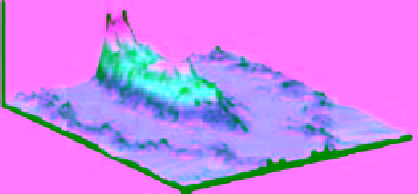
Fig. 9.
Comparison between three-dimensional lobe shapes (dimensions expressed in m). (A) The three dimensional shape
of the lobe for Run 2, obtained from Baas
et al
. (2004). (B) The three dimensional shape of the lobe for Run 2, obtained from
MassFLOW-3DTM simulations with the turbulent mixing scale set to 0.15 mm. (C) The three dimensional shape of the lobe
for Run 2, obtained from MassFLOW-3DTM simulations with the turbulent mixing scale set to 1 mm.
(A)
(B)
0.04
0.04
0.03
0.02
0.01
0
Run 4,
Baas
et al
.,
2004
0.03
0.02
0.01
0
Run 4
Tlen=0.15 mm
Fig. 10.
Comparison between three-dimensional lobe shapes (dimensions expressed in m). A) The three dimensional
shape of the lobe for Run 4, obtained from Baas
et al
. (2004). B) The three dimensional shape of the lobe for Run 2, obtained
from MassFLOW-3DTM simulations with the turbulent mixing scale set to 0.15 mm.


Search WWH ::

Custom Search