Geoscience Reference
In-Depth Information
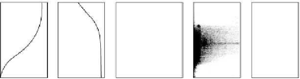
electrojet (Pfaff, 1985). This allows longer-wavelength waves to be studied. The
electric field data from the latter experiment are shown in Fig. 10.28e. The electric
field signal is modulated by the rocket spin. The envelope of this modulation
is smoothly varying above about 102 km. Below this height the spin signal is
modulated by the geophysical phenomenon of interest here. Analysis indicates
that these modulations correspond to roughly a 300m horizontal wavelength for
the electric field fluctuation. These waves occurred in a region of vertical plasma
density gradient (see Fig. 10.28a) and of northward dc electric field. This, of
course, is the proper orientation for instability of the gradient drift wave. Notice
that the waves are localized in altitude even though the near-vertical magnetic
field allows very efficient coupling along
B
. We return to a discussion of this
problem and these same data following.
10.5.3 Simultaneous Data Sets
As in the equatorial case, significant advances are possible when more than one
measurement technique is applied in a given experiment. The data in Fig. 10.28
are of this type, since the incoherent scatter radar at Chatanika was used to
provide the electron density profile shown in panel a as well as the ambient
electric field. Armed with these data, the vertical profile of
V
e
−
V
i
was calculated
(panel b) and the linear theory (see Section 10.6) was used to calculate the growth
rate as a function of wave number in panel c. When compared to the electric
field wave data in panels d and c, it is clear at once that high-frequency (high
k
value) waves are observed in the upper electrojet, where the two-stream term
dominates. However, the long-wavelength waves are present in the bottomside
gradient region, where the quantity
V
d
/(
l
+
ψ)
is below the threshold value
Auroral electrojet - Poker Flat, Alaska
7 March 1981
Spin plane Efields
130
SRI incoherent
scatter radar
120
V
e
2
V
i
110
V
d
Long
wavelength
waves
100
11
Data
c ipped
90
10000
100000
0
200 400 600 0.001 0.01
0.1
1
10
0
2500
5000
2
80
0
80
Electron density (cm
3
)
Velocity (m
/
s)
Wavenumber (m
1
)
Frequency (Hz)
mV/m
(a)
(b)
(c)
(d)
(e)
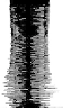
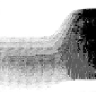
Figure 10.28
Growth rate modeling for the combined two-stream and gradient drift
instability and comparison to the
Auroral-E
data. The model assumes a stable, vertical
electron density gradient as measured by the SRI incoherent scatter radar and a 35 mV/m
ambient electric field. The electron density is assumed to be uniform in horizontal extent.
The in situ measured electric field data are shown in the two panels to the far right. [After
Pfaff et al. (1984). Reproduced with permission of the American Geophysical Union.]


Search WWH ::

Custom Search