Geoscience Reference
In-Depth Information
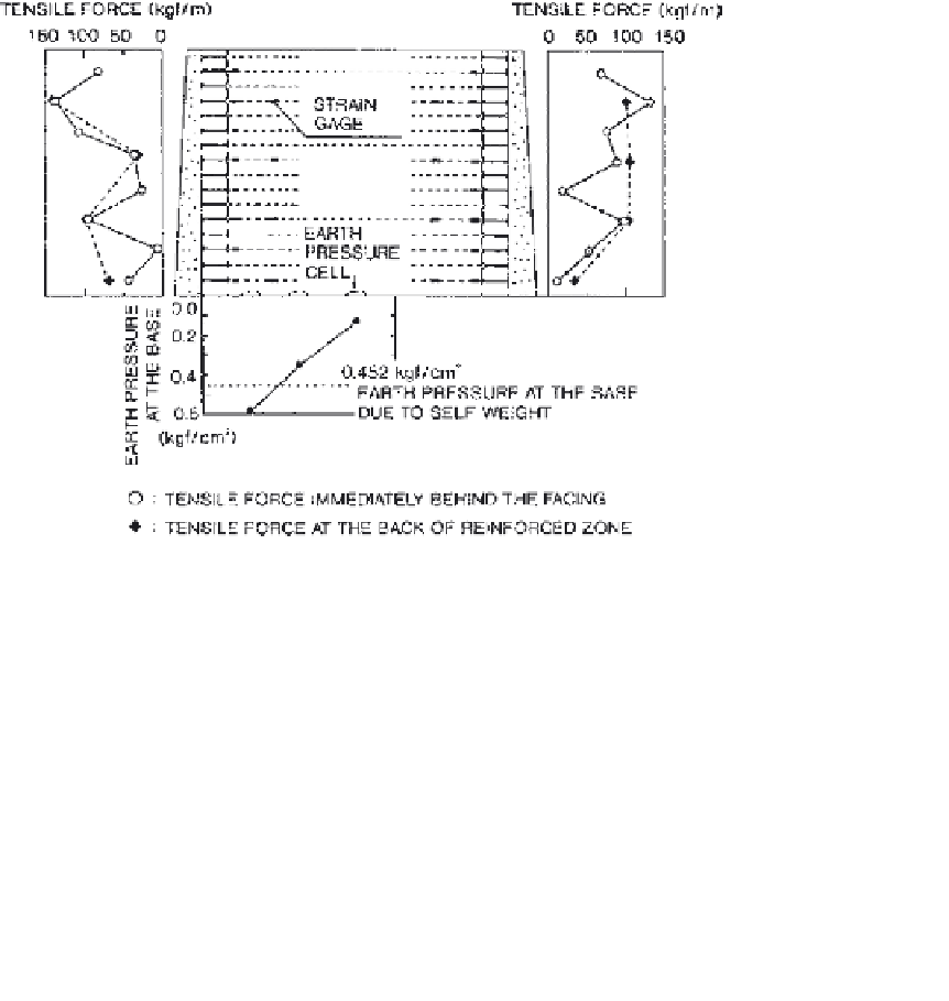
Figure 16
Maximum reinforcement force and vertical stress distribution. (FromMurata
et al., 1994.)
(Miyatake et al., 1995; Tajiri et al., 1996). The material properties of soils and
geosynthetics were well defined. The geometry of the PWRI wall is shown in
Fig. 17
.
It was 6m high and 5 m wide, constructed in a concrete test pit on a
concrete floor. The sides of the wall were lubricated using grease and polymer
sheets. A silty sand (D
50
¼
16.0 kN/m
3
) was used as backfill.
The stress-strain properties of the sand were also measured and reported by Ling
et al. (2000).
A uniaxial geogrid (Tensar SR55), manufactured from high-density
polyethylene (HDPE), was used as reinforcement. The spacings between the
longitudinal and transverse ribs were 2.2 cm and 16.6 cm, respectively. The
strength of the geogrid was 55 kN/m. The PWRI wall consisted of six primary
and five secondary geosynthetic layers, each 3.5 m and 1.0 m long, respectively.
The geosynthetic layers were bolted to the concrete blocks with the bolts and
metal frame as shown in Fig. 17. (Note: Because of this bolting connection, it is
considered different from the modular block wall.) A total of 12 concrete blocks
was used along the wall height. Each block was 50 cm high and 35 cm wide,
except the top and bottom blocks, which were 45 cm and 55 cm high,
respectively.
¼
0.42mm, g


Search WWH ::

Custom Search