Geoscience Reference
In-Depth Information
4 MODEL GEOMETRY AND INPUT PARAMETERS
A cross section of the highest portion of the double-wall reinforced earth
approach embankment was modeled in two dimensions assuming plane strain
conditions, as shown in
Fig. 3
.
At this maximum wall section, the wall is 10m high and steel strips with a
cross-sectional area of 40mm
5mm and length of 7m were used. Design
drawings indicate that the reinforcements were placed with a horizontal-to-vertical
grade of 5%. Four strips were used per panel in most cases, although five strips were
used per panel for the two lower panels of themaximumwall section beingmodeled.
The embankment is 12.5m wide, resulting in a 1.5m reinforcement overlap at the
wall center for the cross section considered. As shown in Fig. 3, the reinforcements
were not connected at the overlap zone.
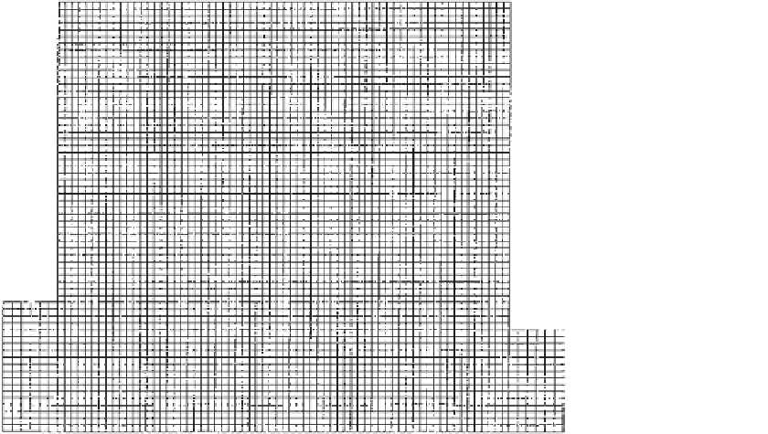
For modeling purposes, the cross section was discretized into zones of sizes
18.75 cm
£
18.75 cm; see Fig. 5. Thus, the analyzed cross section was divided
into 67 zones in the horizontal direction and 53 zones in the vertical direction.
This discretization provided sufficient accuracy to capture the stresses and
displacements in the soil and reinforcements, while keeping computation time
£
Figure 5
Finite-difference grid used in the static and dynamic analyses.


Search WWH ::

Custom Search