Geoscience Reference
In-Depth Information
The initial stress in the soil mass was generated using the K
0
procedure,
where the horizontal effective stresses were computed as K
o
times of the vertical
effective stresses. As the RS wall was constructed above ground level; the water
table is at depth of 10m below ground level; the GWT is placed at the base of the
FEM model. After the initial stress in the soil was generated using the K
0
procedure, there were unbalanced forces in the soil near to the vertical free
surface. Hence, a nil-step was implemented to zero out the unbalanced forces.
procedure before and after the nil-step. After the nil-step, the horizontal stresses
near the free surface of the wall were reduced to zero. The equilibrium stress
conditions of the soil after the nil-step of Fig. 16 are now used as the initial stress
condition of the wall prior to the blast loading.
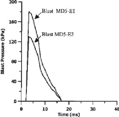
Dynamic analysis of two blast events of different blast magnitudes was
carried out. The dynamic analysis option was selected in the calculation step
when applying the blast loading on the wall. In the dynamic analysis, the time
span is in milliseconds. The blast pressure acting on the wall was simulated by
applying a uniformly distributed load on the wall front, which increases in
magnitude instantaneously to its peak value and then gradually decreases to zero
after a short duration (Yogendrakumar and Bathurst, 1993). The magnitude of the
uniformly distributed load was made to vary with time by applying a total
multiplier of varying magnitude with time based on the input text file. Fig. 17
shows the blast pressure-time histories for the two events, MD5-E1 with peak
Figure 17
Blast pressure-time histories for the blast events MD5-E1 and MD5-E2,
with peak pressures of 180 kPa and 130 kPa, respectively.


Search WWH ::

Custom Search