Geoscience Reference
In-Depth Information
of the GRS walls were conducted under a quality assurance system. This means
that there were a number of check/hold points in both the design and construction
processes. The success of this project under such a demanding contractual
environment attested to the effectiveness of GRS walls. The tallest GRS wall for
the M2 project was 18.71 m. It was founded directly on sandstone bedrock, but
the possible presence of weak horizontal bedding joints was considered in the
design. This wall section is a stepped wall (see
Fig. 15
)
constructed from three
different grades of reinforcing straps and utilizing six different horizontal
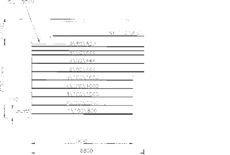
spacings. A number of abutment walls that directly support bridge decks were
constructed. One such wall section is shown in Fig. 16. The sill beam is about
25.7m in length. The design vertical loadings from the bridge deck are 8400 kN
and 2460 kN for dead and live load respectively. The top 2 to 2.5m of in-situ
material below the foundation level were replaced by crushed sandstone
compacted to a target dry density of 18.5 kN/m
3
. This layer is underlain by
sandstone bedrock. An inverted tee-shape sill beam contributed to minimizing
the end rotation of the bridge deck (due to the tilt of the sill beam). It is important
to backfill behind and against the sill beam before placement of bridge beams.
Figure 16
GRS wall supporting bridge deck.


Search WWH ::

Custom Search