Geoscience Reference
In-Depth Information
Table 3
Characteristics of the Fill Materials
c
0
(kPa)
f
0
(deg)
D
10
(mm)
D
50
(mm)
g
(kN/m
3
)
Structure
Type of soil
G
C
u
Sau´pe
Silty sand
2.66
0.001
0.20
280
19.9
31.8
36.1
Suba´ma
Clayey sand
2.64
0.0002
0.21
1350
19.8
29.2
37.8
B´
Clayey sand
2.66
0.0001
0.25
3000
20.2
16.3
41.1
Mucambo
Sand
NA
NA
NA
NA
18.5
0
29.9
Itarir´
Sand
NA
NA
NA
NA
20.1
4.6
28.1
NA
specific
weight, effective cohesion, and effective friction angle at optimum moisture content, respectively.
G
¼
specific gravity of the soil particles, D
10
and D
50
¼
particle diameters corresponding to 10% and
50% passing, respectively, C
u
¼
coefficient of uniformity (
¼
D
60
/D
10
).
¼
value not available. c
0
and f
0
obtained from drained direct shear tests. g, c
0
, and f
0
¼
a square pattern), as shown in
Fig. 6.
The rest of the embankment was built on
the same type of piles and caps (1
0.3m) with a layer of geotextile on top
(Fig. 6). The soil used in the embankment was a fine sand (Table 3). The
foundation soil of this wall is composed by a 2-m-thick layer of clayey sand
over a soft organic clay layer with undrained strength typically varying between
also employed as reinforcement for this structure. The spacing between
geotextile layers used was equal to 0.3 m and the reinforcement length was
equal to 3.25m.
£
1
£
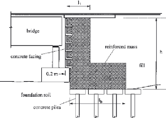
Figure 4
Schematic cross section of the Bu River reinforced abutment.


Search WWH ::

Custom Search