Geoscience Reference
In-Depth Information
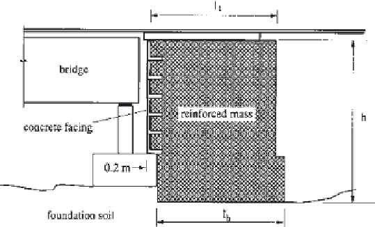
Figure 3
Schematic cross section of Sauipe River reinforced abutment.
work, as commented above. The spacing between reinforcement layers was
0.3m, and the length of the reinforcement was equal to 3.2m. It can be observed
that the designers heavily reinforced the embankment, aiming for a more uniform
settlement distribution.
2.2.2 Bu River Structure
This retaining wall is 7.3 m high and its general characteristics are schematically
shown in
Fig. 4
.
Additional information on the reinforcement layout can be found
in
Table 2
.
Because of the high compressibility of the foundation soil in this case,
the reinforced structure was supported by 0.25-m-diameter piles with caps
(1
0.3 m) with 1.25-m spacing distributed in a square pattern. The soil used
in the embankment was a clayey sand whose properties are presented in
Table 3
.
The foundation profile
(Table 1)
shows the presence of a 2.5-m-thick clayey sand
layer on a 3.6-m-thick organic silty clay deposit. Nonwoven geotextile A
(Table 4)
was used as reinforcement in this case. The distribution of
reinforcement layers along the wall height was divided in two parts (Fig. 4 and
Table 2). In the lower part (up to 2.5m above the base of the wall) the spacing
between reinforcement layers was equal to 0.2 m with a reinforcement length of
8.9m, while in the upper part of the wall the spacing between reinforcements was
equal to 0.3 m with 3.2-m-long reinforcement layers.
£
1
£
2.2.3 Subauma River Structure
The reinforced structure used in the abutment for the crossing of the Subauma
River was only 1.75m high and was also built on 0.25-m-diameter concrete


Search WWH ::

Custom Search