Geoscience Reference
In-Depth Information
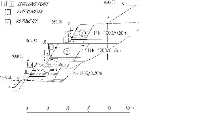
The selected reference points were obtained with special plates, fixed to the
wire mesh facing and to the heads of the extensometers. Station points for
surveying were set on the opposite bank of the river, at distances not exceeding
100 m. The location of the reference points for cross section 12 are shown in
Fig. 3. Plates and extensometers in Section 6 are arranged in a similar way.
Time histories of horizontal and vertical displacements are shown in
Fig. 4
.
Most curves exhibit a sharp rise soon after new fill is added, during construction.
As time goes on, the curves smooth toward a horizontal asymptote.
At Section 6, the maximum horizontal displacements is in the order of
70 mm, on the lower plate of the lowest block. The upper blocks exhibit lesser
horizontal displacements, in the order of 50mm. Vertical displacements range
between 30 and 45 mm.
At Section 12, the measured horizontal displacements of the lower block
are somehow larger, with a maximum in the order of 100mm. The horizontal
displacements of the upper blocks were approximately 50mm. Vertical
displacements are about 70mm, in the lower block, and 40mm, above.
Displacement vectors are shown in
Fig. 5
.
The horizontal component gen-
erally exceeds the vertical one, throughout the time of observation. The resulting
Figure 3
Design cross section 12 with blocks numbering,
reinforcements, and
instrumentation.


Search WWH ::

Custom Search