Geoscience Reference
In-Depth Information
Location (
X
)
Location (
X
)
a)
Reflector
Actual structure
Location (
X
)
Location (
X
)
b)
Zone of
higher seismic
velocity
Reflector
Actual structure
Phantom diffraction
Location (
X
)
Location (
X
)
c)
Point diffractor
Point diffractor
Point diffractor
Actual structure
Location (
X
)
Location (
X
)
d)
Reflector
Actual structure
Location (
X
)
Location (
X
)
e)
Response from dipping interface
Reflector
Actual structure
Actual structure
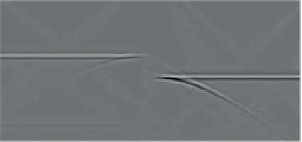
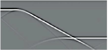
Figure 6.22
Some common subsurface structures and their representation in unmigrated normal-incidence seismic reflection data. Selected
raypaths are shown. (a) Horizontal reflector, (b) horizontal reflector with lateral change in velocity, (c) diffractions, (d) horizontal stepped
reflector, (e) dipping step reflector, (f) antiform and (g) synform. Velocity is constant in all figures except (b). The seismic velocity is 2 km/s, so
that the TWT and depth scales are equivalent, allowing
'
actual structure
'
to be overlaid on the seismic data.
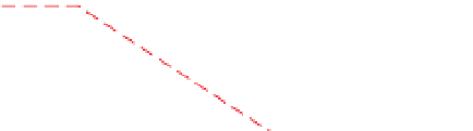
point diffractors. The concept is useful for explaining
migration.
Figure 6.23a
shows zero-offset data produced
by a series of equally spaced diffractors located at the same
depth. The data are the zero-offset equivalents of the
offset wavefields shown in
Fig. 6.11
. As shown in
Fig. 6.22c
,
each diffractor produces a characteristic hyperbolic
response with its maximum amplitude at its apex. Where
the hyperbolae
finite-
intersect
they
interfere, with the


Search WWH ::

Custom Search