Geoscience Reference
In-Depth Information
a)
b)
CMP
Offset (
X
)
Sources
Detectors
T
0
(Refl #1)
V
1
V
a
=
V
rms
(V
1
)
V
1
T
0
Reflection
#1
(Refl #2)
V
b
=
V
rms
(V
1
,V
2
)
V
2
V
2
Reflection
#2
Reflection
#3
T
0
(Refl #3)
V
3
V
c
=
V
rms
(V
1
,V
2
,V
3
)
V
3
Depth
(
Z
)
V
4
Time
(
T
)
V
V
V
V
V
3
>
V
2
>
V
4
3
2
1
1
c)
Offset (
X
)
Offset (
X
)
Offset (
X
)
Offset (
X
)
Offset (
X
)
Offset (X)
T
0
(Refl
#1)
T
0
(Refl
#2)
T
0
(Refl
#3)
Time
(
T
)
Time
(
T
)
Time
(
T
)
Time
(
T
)
Time
(
T
)
Time
(
T
)
Velocity <
V
a
Velocity =
V
a
Velocity =
V
b
V
b
< Velocity <
V
c
Velocity =
V
c
Velocity >
V
c
Increasing NMO correction velocity
Stacking
velocity (
V
Stack
)
d)
e)
f)
g)
Offset (
X
)
O
ff
s
et
(
X
)
V
a
V
b
V
c
Reflection
#1
T
0
(Refl #1)
T
0
(Refl #1)
T
0
(Refl #1)
T
0
(Refl #1)
Muted
Muted
Velocity-time
function
T
Near
Reflection
#2
T
0
(Refl #2)
T
0
(Refl #2)
T
0
T
0
(Refl #2)
(Refl #2)
T
Far
T
0
(Refl #3)
T
0
(Refl #3)
T
0
(Refl #3)
Reflection
#3
T
0
(Refl #3)
Flatten
(NMO correction)
Stacked
trace
Two-way
time
(TWT)
Two-way
time
(TWT)
Two-way
time
(TWT)
Two-way
time
(TWT)
Summation
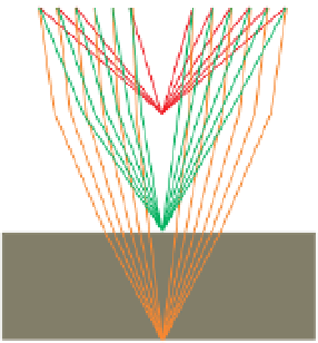
Figure 6.21
Schematic illustration of the procedure for determining the NMO correction. See text for explanation.


Search WWH ::

Custom Search