Geoscience Reference
In-Depth Information
AB
V
1
+
BC
V
1
Midpoint
T
Refl
¼
T
AB
+
T
BC
¼
ð
6
:
17
Þ
Source
Detector
Source
Detector
If the raypath is used to construct a right-angled triangle
with hypotenuse AB + BC and the two other sides of length
X(X
AC) and 2Z, then it is clear that
Eq. (6.17)
can be
written as:
¼
V
V
1
1
q
X
2
Raypath
without
refraction
V
V
2
2
+
ð
2Z
Þ
2
T
Rfl
¼
ð
6
:
18
Þ
V
1
V
V
3
3
When discussing stacking it
is convenient
to express
V
VV
V
3
>
V
2
>
V
1
the travel
ections in terms of a constant
component (T
0
) and a variable component, which is the
increase in time relative to T
0
with source
times of re
2
1
3
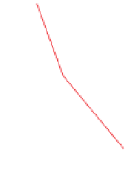
Figure 6.15
Refracted (minimum time) and non-refracted (minimum
length) raypaths of reflected arrivals for a three-layer Earth model.
detector offset
(X). Moveout relative to the zero-offset time is known as
normal moveout (NMO). For offsets which are small
compared with Z the following approximation expression
can be used:
-
contrasts, the travel time for a re
ection from a deeper
(6.20)
. The (constant) velocity of the material overlying the
re
ector (V
1
) is replaced by the root-mean-square velocity
(V
rms
) of the layers overlying the reflector (the root-mean-
square is a form of average, literally the square root of the
mean of the squares of the velocities). The velocity of an
individual layer is known as the interval velocity (V
int
).
This can be determined for each layer once V
rms
for reflec-
tions from the top and base of the layer are known, using
the Dix (
1955
) equation:
X
2
2V
1
T
0
T
Rfl
≈
ð
:
Þ
T
0
+
6
19
Figure 6.14b
shows re
ections from several interfaces. The
arrivals again have curved moveout. A series of actual
re
ected arrivals can also be seen in the real data forming
from deeper interfaces is markedly less than that from the
and because velocity also tends to increase with depth (see
be used to determine the velocity of the overlying layer
s
V
rms
n
T
n
V
rms
n
1
T
n
1
T
n
V
int
¼
ð
6
:
21
Þ
T
n
1
where the subscript n refers to the velocity and time for the
reflection from the lower interface of the nth layer, and n
1
the same from the interface above it. A comprehensive
description of velocity information derived from reflected
-
4Z
2
V
1
+
X
2
V
1
¼
X
2
V
1
T
Rfl
¼
T
0
+
ð
:
Þ
6
20
2
versus X
2
is a straight line with intercept T
0
2
and slope 1/V
1
2
.
In
Fig. 6.14b
there are no differences in velocity between
the various layers so there is no refraction of the rays as
they cross the interface (see
Section 6.3.4.2
)
.
Figure 6.15
shows re
ections from planar interfaces across which the
velocity changes. The velocity contrasts between the layers
refract the raypaths of the re
ections from the deeper
interface, changing their lengths and travel times. The
effect is greater at longer offsets and for larger velocity
contrasts. These are the minimum travel time paths. Also
shown in the
figure are the equivalent non-refracted
(minimum-distance) raypaths. In the presence of velocity
A plot of T
R
Multiples
Arrivals re
ected only once during their journey through
the subsurface are known as primaries. Arrivals that have
been re
ected more than once during their journey are
known as multiples (
Fig. 6.14b
)
. They are categorised as
either long- or short-period. The former have paths suffi-
-
ciently different from their primary that distinct arrivals
are observed in the survey data. Long-period multiples
from a shallow re
ector can easily be mistaken for primar-
ies from a deeper re
ector. They are a signi
cant source of
methodological noise (see
Section 2.4.2
), especially in
waterborne surveys.


Search WWH ::

Custom Search