Geoscience Reference
In-Depth Information
a)
a)
Transmitter
Tx
EM receiver
bird
Receiver
(retracted)
100
-
130 m
Magnetometer
Centre
of Tx loop
Transmitter loop (slung
from nose, tail and
wing tips)
b)
Magnetometer
bird
EM receiver
bird
90
-
120 m
70
-
80 m
b)
Magnetometer
bird
Receiver
Rx
60
-
70 m
Tx
30
-
40 m
Transmitter
Magnetometer
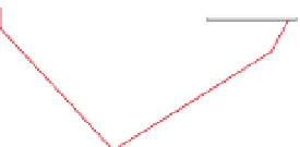
Figure 5.98
Schematic illustrations of a)
fixed wing and b) helicopter
AEM systems.
Figure 5.99
Examples of AEM systems. (a) TEMPEST
fixed-wing
towed-bird system. Courtesy of CGG. (b) SkyTEM helicopter
system. Courtesy of SkyTEM Surveys.
which appear as noise in the measured response. This,
along with the noise from all other sources, reduces system
sensitivity at late decay times. Furthermore, variations in
transmitter to receiver separation cause variations in the
on-time measurements (see
Section 5.9.1.2
). The monitor-
ing of bird location and motion with respect to the trans-
mitter loop allow a correction to be applied to the data.
The separated-loop con
guration has asymmetric geom-
etry. The array changes orientation on reciprocal survey
headings so the response is asymmetric and there is an
offset in its location between survey lines flown in the
opposite direction (as demonstrated by the differences in
the model responses in
Figs. 5.85
and
5.86
). Also, the
polarity of the X-component data is reversed. These are
not major problems when analysing individual line-profiles,
but are a signi
cant disadvantage when compiling 2D
images of the measured parameters, as processing artefacts
are caused by the asymmetry. When displaying
X-component data, their polarity for alternate headings may
be reversed to facilitate inter-line comparison of responses.
Fixed-wing towed-bird AEM systems
y at a survey speed
of 180
-
250 km/h (50
-
70 m/s) at 90
-
120 m above the terrain
with the towed receiver 70
80 m above the ground
(
Fig. 5.98a
). The along-line data interval is typically about
15 m. The area of the transmitter loop and the number of
turns in it vary from system to system, with dipole moments
ranging from about 500,000 to 2.2 million A m
2
.
-


Search WWH ::

Custom Search