Geoscience Reference
In-Depth Information
a)
Dykes with copper
mineralisation
Post-older volcanic sequence
Probable limit >0.4% Cu
Older volcanic
sequence
Alluvium
Butte fault
0
1
Dominant Cu sulphides
Pyrite halo with minor Cu sulphides
Intrusions
Galena + Au occurrences
Kilometre
b)
SP contours (mV)
CI = 500
>1000
750
1000
500
<1000
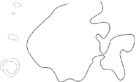
Figure 5.32
Safford porphyry Cu deposit.
(a) Summary geological map showing the
distribution of sulphide mineralisation.
(b) Contours of surface SP. Note the
correspondence between the main SP anomaly
and the mineralisation within dykes. Redrawn,
with permission, from Robinson and Cook
(
1966
).
0
1
Kilometre
environmental studies. In mineral exploration, measure-
ments are usually made of both parameters, resistivity data
being acquired as part of the IP surveying methodology,
with the analysis of each complementing the other.
by a battery or a portable generator is applied to the
ground via a pair of electrodes known as the current
electrodes, which form the current or transmitter dipole.
An electric
field is formed in the ground, resulting in
current
flow through the subsurface, which is measured.
Differences in electrical potential between selected loca-
tions, owing to the subsurface current
ow, are measured
using a second pair of electrodes known as the potential
electrodes, which make up the potential or receiver dipole.
The layout or con
guration of the four electrodes is known
as an electrode array. At each survey station, the transmit-
ted current and the measured potential difference across
the receiver dipole are recorded along with the location of
the four electrodes. From these data the resistivity of the
subsurface can be calculated, as described in
Section 5.6.2
.
The IP response is also recorded and the various IP par-
ameters calculated as described in
Section 5.6.3
.
Lateral and vertical variations in resistivity/IP properties
of the subsurface can be mapped by moving the array
around the survey area and by changing the relative pos-
itions of the electrodes making up the array. Data may be
acquired and presented in the form of pro
les (1D), maps
or cross-sections (2D), or volumes (3D). Like many types
of geophysical data, assigning a depth to a particular meas-
urement can be problematic. Usually the potential and the
current electrodes are located on the surface of the ground,
but one or more electrodes may be located in one or more
drillholes which can lead to signi
cant improvements in
target detection and resolution. A common form of down-
hole resistivity surveying is the applied potential method
described in
Section 5.6.9
. Also common is downhole


Search WWH ::

Custom Search