Geoscience Reference
In-Depth Information
Sensor
TDR unit
Tr ansmission line
Length
L
Volts
Time
t
Time
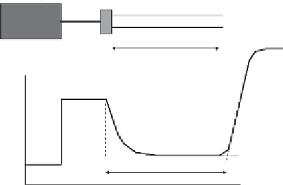
Figure 4.30
Setup of the time domain relectrometry method.
data have been collected, but these methods have two main disadvantages: the invis-
ible danger of nuclear radiation and the need for site-speciic calibration. These dis-
advantages were eliminated with time domain relectrometry (TDR). In this method,
a so-called TDR unit emits electromagnetic waves along two or three parallel trans-
mission lines that are installed in the soil (
Figure 4.30
). The relections of the emitted
waves can be visualized with an oscilloscope as function of time or distance. These
relections contain information on the velocity of the electromagnetic wave in the
soil. This velocity appears to be a direct function of soil water content, which can be
explained as follows.
The dielectric behaviour of a material is physically characterized by its
permit-
tivity
. The relative permittivity,
ε
, of a material is generally deined as the factor
by which the capacitance of a plate capacitor increases when the vacuum or air
between the plates is replaced by that material. Thus, per deinition, for vacuum
and air
ε
= 1. Relative permittivities are also called dielectric constants, which is
somewhat misleading as
ε
varies with electromagnetic frequency, temperature, and
water content.
The permittivity depends in the irst place on the polarization in an electrical ield.
The permanent dipole of water molecules yields the extremely high permittivity
ε
water
≈ 81 (at 18 °C), whereas for most mineral soil components,
ε
soil
≈ 5. Owing to
this large difference, the volumetric water content
θ
of a soil can be determined indi-
rectly by measuring its effective permittivity,
ε
, if the calibration relationship
θ
(
ε
) for
the particular soil and dielectric measuring equipment is known. According to basic
physics, the propagation velocity,
v
, of an electromagnetic pulse travelling along a
wave guide is:
c
v
=
ε
(4.47)

Search WWH ::

Custom Search