Geoscience Reference
In-Depth Information
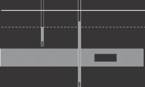
Soil surface
Groundwater level
Phreatic aquifer
Filter
Aquitard
Second aquifer
Filter
Figure 4.26
Setup of two piezometers to determine the seepage across an aquitard.
Question 4.17:
Consider a situation as depicted in
Figure 4.26
. In the shallow tube the
ilter is at
z
= -170 cm and we measure a water level at
z
= -80 cm. In the deep tube
the ilter is at
z
= -350 cm and we measure a water level at
z
= -55 cm. The saturated
hydraulic conductivity of the aquitard equals
k
s
= 1 cm d
-1
, the thickness of the aquitard
equals 50 cm.
a) Calculate the hydraulic head of both tubes.
b) Calculate the soil water pressure head at both ilters.
c) How large is the upward seepage lux density?
4.10.2 Tensiometer
Piezometers cannot be used to measure
negative pressure heads
in the vadose zone,
because any water in the tubes will be adsorbed by the soil. Negative pressure heads
are measured with so-called tensiometers. A tensiometer consists of a liquid-illed
unglazed porous ceramic cup connected to a pressure measuring device, such as a
vacuum gauge, via a liquid-illed tube (
Figure 4.27
). If the ceramic cup is embedded
in soil, the soil solution can low into or out of the tensiometer through the very small
pores in the ceramic cup. Analogously to the situation discussed for piezometers, this
low continues until the pressure head of the water in the cup has become equal to the
soil water pressure head around the cup.
The vacuum gauge does not indicate the pressure in the cup when there is a differ-
ence in height between the two, such as in
Figure 4.27
. The liquid in the tube between
the cup and the vacuum gauge is at static equilibrium and thus the pressure in this
liquid increases linearly with depth. Therefore the pressure head of the liquid in the
cup is:
hh
= + +
gauge
∆∆
z
z
2
(4.44)
1
Search WWH ::

Custom Search